
1,706 total views, 1 views today
April 29, Work In Progress, will expand as Time Permits
May 02 added Photos
May 06 added Photos
Boom to Fuse
Slide the control cables thru the openings at the fuse top, and the ends thru the holes in the bulkhead behind the servo tray.
The clevis ends may need to be turned a bit to align with the bulkhead holes.
Then slide the boom through the round opening most forward on fuse top.
Then the wing rod as well as the incidence can can be pushed thru the fuse and boom
Locate the two boom hold down screws and insert and tighten these.
Next secure the control cable end with the cable clamp forward of the bulkhead just behind the servo tray.
Secure clevises to stab and rudder servo horns.

Secure the fuse to the stand, this thing is like a ball and wants to roll away

locate the hole in the bulkhead behind the servo tray for the rudder control cable. There are two correct holes to use which will align with the servo horns and the cable clamp.

as well as the hole for the stab control cable


Feed the control cables down thru these two openings between bulkheads, easiest with the two clevises removed

use some type of hook to feed the ends of both cables thru the appropriate holes in the bulkhead
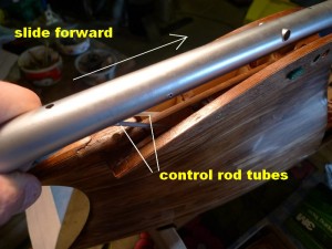
Once the cables are moving freely thru the holes in the bulkhead and not fetching on the forward side you can proceed with sliding the boom forward to align the screw holes

Engage the boom in the wing root LE opening prior to moving the boom the last inch or so to align the wing rod holes

place the wing rod and incidence pin then secure the boom with the two screws

Next check for the correct alignment of the control cable clamp above the servo tray and select a small common screw driver with a long enough blade to reach the screw and tighten

Pass the screwdriver thru the opening between the boom and the fuse, and set at an angle to access the slot in the screw and tighten the clamp while keeping it aligned so as not to incorrectly squeeze the tube
Wings to Fuse
Wing has a flying lead connector.
I like to get the wing on far enough onto the dihedral pin as well as the main wing rod, then there is enough room between the fuse and the wing root to connect to multiplex connector to the receptacle in the fuse root section.
Multiplex connectors are keyed so they only fit together one way.
Once the wings are in place the Fuselage Cap is added, made of thin birch ply this is spread apart at the rear to fit over the boom and then set down tight to the top of the fuselage.

A set of interlocking tabs on the underside of the cap and on the fuselage are used to hold the cap tight to the fuselage at the rear

The rear wings of the cap are spread apart to fit over the boom and the rear edge is held down forward of the alignment line before it is slid rear ward. Note, when removing the line must be visible, slide cap forward, before spreading and lifting the cap away
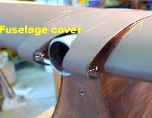
Once the rear of the cap(cover) is in place under the boom the front is pressed down , and with care while holding the rear and front down the cap is slid rearward.

Prior to adding the boom end cap the cap is slid rearward and tight

Boom end cap holds the cap in place at the front
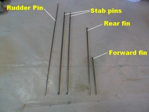
Fin and Subfin
Lower sub fin is placed over stab control horn prior to engagement of pins
These pins are a firm fit into the sub fin

Place both pins thru only when lower sub fin is over stab control bell crank, and all pin holes are aligned . Engage forward pin then rear pin, and set down until they bottom. This is a firm fit
Once lower sub fin is in place upper fin can be set down over the two pins. These fins are friction fit on the rods, perhaps a bit of wax on the pins before the upper fin is placed would be helpful.
Rudder cannot be placed onto the hinges on fin and sub fin unless they are firmly placed against the boom
Stab set
There is a left and a right for these as the underside is flat and the upper side is curved. There are down arrows on the root face, so left and right can be easily identified. If the two pins are not in place then I suggest the forward pin be placed first as it also engages into the forward hole of the bell crank. A flashlight would come in handy, to look into the boom end to align the forward hole in the bell crank with the corresponding holes in the boom before sliding the pin thru.
The rear pin passes thru the slots in the fuse and the rear hole in the bell crank, A little wax on the rods would help retain the stabs.
Rudder.
The rudder is held to the fin and subfin with a pin that passes thru the 3 sets of hings and engages starting at the lower set.
Insert up from the bottom
Make sure the fin and subfin are tight against the boom before hand.
As you push the pin thru a bit of careful movement is necessary to align the hinges and engage the pin especially the top most hinge set
Canopy removal
This fits snug between the forward nose piece and the bulkhead in front of the servo tray. It is held secure with a set of magnets at the front, and with a trim piece that is fit under the boom at the rear and held secure with the white button screw.
This trim piece needs to be removed and withdrawn by pulling it forward from the top.
The canopy is best grabbed at the front and then slid straight up to remove it from the fuselage, such to not force the nose piece at the top.
Seat
The seat sets into the groove at the rear of the canopy, and over a cross member at the bottom and is held in place with magnets.
Bim Bam Bino should be secured in for any Test Flights

Perhaps with a belt around his waist.
Wing Struts
These are engraved on the ends to ID the Fuse end Left / right as well as wing end, and are held in place with screws into corresponding T Nuts.
Balance