
4,229 total views, 4 views today
 THE Troodon Build
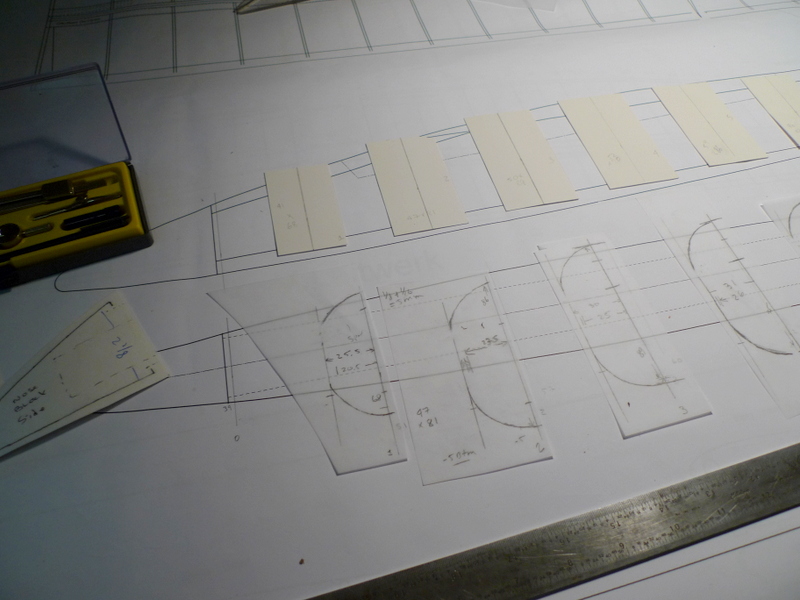
Woo hoo, we have Plans, Troodon and ribs not much else though
From Plans Nov 05, very much a Scratch Build Plane gonna be at this for a bit I reckon, should be fun though.
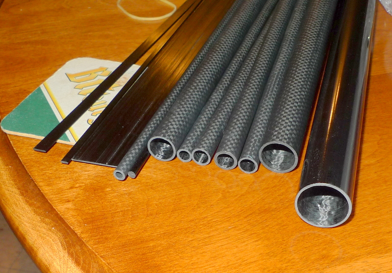
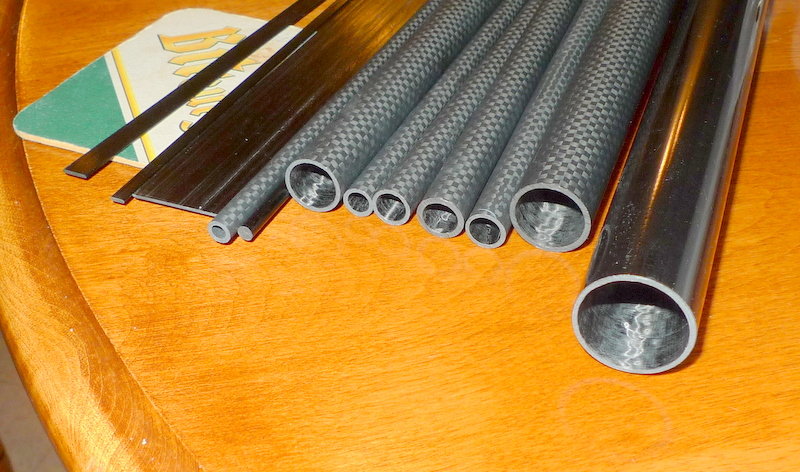
Tubing needed for wings, tail all the lengths can be measured off the plans
- 3mm – leading edges
- 4mm
- 6mm
- 8mm
- 10mm
- 12mm
- 15mm
- 20mm
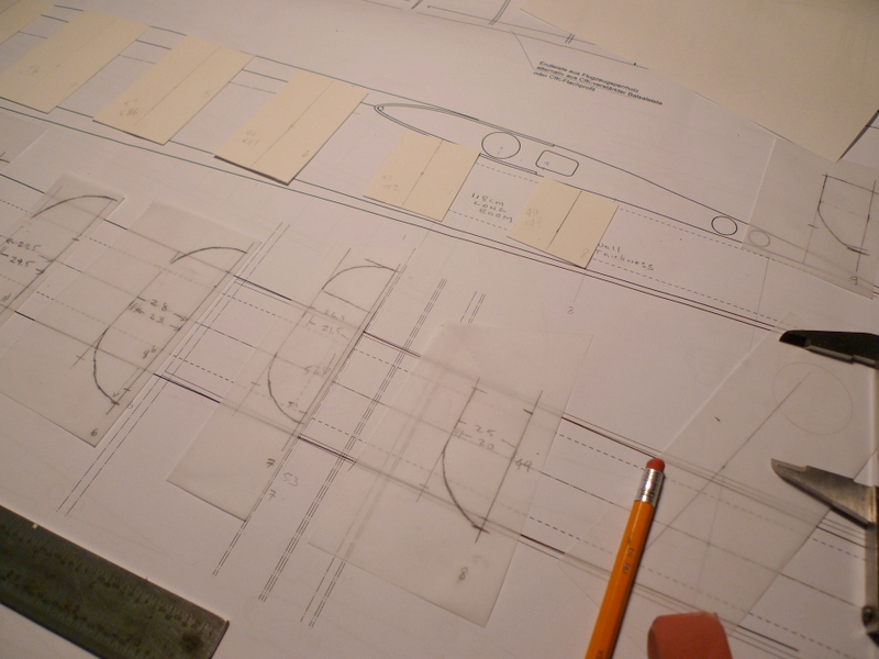
Fuselage ( some additional Info)
50 deep x 40 wide by the le and 70 deep and 40 wide halfway......made to fit the
servos  batt etc.
1.1 meter from the rear bolt to the hing line on the rudder
Yoke home made but from CF perfect.
Main spar tubes made for >> me,,,,,UD   (uni Directional  WH) >> carbon very
 strong,

>>> but
>>> there are many available in Europe. > No diagonal ribs, >> Just 3 x 5 mm
>> hard > balsa strips > Fuselage, just 5 and 10 mm plus some >> block >>
>> balsa
>> sanded > to shape and skinned > in carbon and painted. >
Wing MAke sure that main spar tubes are VERY strong and will not twist!!!! Yes, D box
sheeted.
A carbon skin. But hard balsa is fine Yes about .5 carbon, or .5 ply
Nov 06
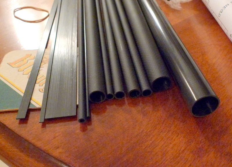
Consider tubes 1.5 MM wall for main panel, 1 MM for the tip panels

3k CF tube Matt Twill
Mr C has 11 Types of Cf sheet tube in Factory
1. 3K Roll 100% Carbon fiber Round Tube-Light-Plain
2. 3K Roll 100% Carbon fiber Round Tube-Light-Twill
3. 3K Roll 100% Carbon fiber Round Tube-Matt-Plain
4. 3K Roll 100% Carbon fiber Round Tube-Matt-Twill
5. 100% Carbon fiber Round Tube-Original black
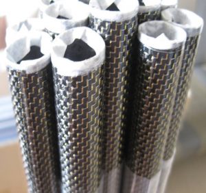
6. 100% Carbon fiber Square tube-Original black(Square hole / Round hole)
7. 100% Carbon fiber Round Rod-Original black
8. 100% Carbon fiber Square Rod-Original black
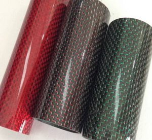
9. 3K 100% Carbon fiber cloth-with black and other colors
10. 3K 100% Carbon fiber cloth-Plating Silver (Plain/Twill),This is the first choice for DIY, it can be spray the color of your favorite.
11. 3K 100% Carbon fiber sheet/plate-Light/Matt-Plain/Twill (Cut by CNC according to your drawings.)
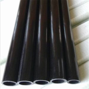
100% CF tube black
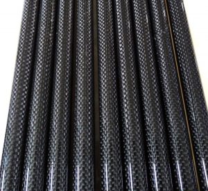
3k-tube-plain-twill-light-matt
Nov 08
Ultracote is on it’s way….for an idea of what I’m thinking (currently) just picture trans blue on the center panel, with a white fuse and black boom. I may use that lite trans white
as well perhaps mid span, but I also have some fluorescent trans yellow on the way just to see what it looks like…..
Boom 35 to 25 mm 1.2 meter long 1.2 to 1.5 mm thick
My take on CF needed, your mileage may be different, a Scratch Builders Kit for sure
| Center
Panel |
Horizontal
Stab |
Vert
Stab |
Int.
Panel |
Tip
Panel |
|
|---|---|---|---|---|---|
| 3mm | 1 x 1.6M | 2 x 50 cm | 1 x 40 cm | 2 x 50 cm | |
| 4mm | 2 x 62 cm | 2 x 50 cm | |||
| 6mm OD – 4mm ID | 2 x 50 cm | 1 x 40 cm | 2 x 62 cm | ||
| 8mm OD – 6mm ID | 1 x 10 cm
1 x 40 cm |
2 x 62 cm | |||
| 10mm OD – 8mm ID | 1 x 1.6M | 2 x 50 cm | |||
| 12mm OD – 19mm ID | 1 x 1.6M | ||||
| 15mm OD – 13mm ID | 2 x 62 cm | ||||
| 20mm OD – 17mm ID | 1 x 1.6M 1 x 40cm | ||||
| 3/16″ Rod or 4mm | 2 x 12 cm | ||||
| 6mm Rod | 1 x 11 cm | 2 x 8 cm | |||
| 8mm Rod | 2 x 12 cm | ||||
| Trailing edge .8mm x 25.4mm
Rectangle |
2 x 1M | 2 x 50 cm | 1 x 40 cm | 2 x 62 cm | 2 x 50 cm |
Mr C cannot provide tapered tube, have found another source, and inquired
will still offer list for rest of CF to him to get a Quote Shipped
Nov 10
All trailing edges 1 mm thick CF will get the width from the plans. and notch ribs to suit.
Consider applying a thin cap strip over top to strengthen joint
I’m beginning to see this come together with CF tubes in the fuse boom back to the tail

Servos
6100 and 6125e(stab) for the fuse
6125 minis for the wing
4 cell Eneloop for the battery.
Nov 16
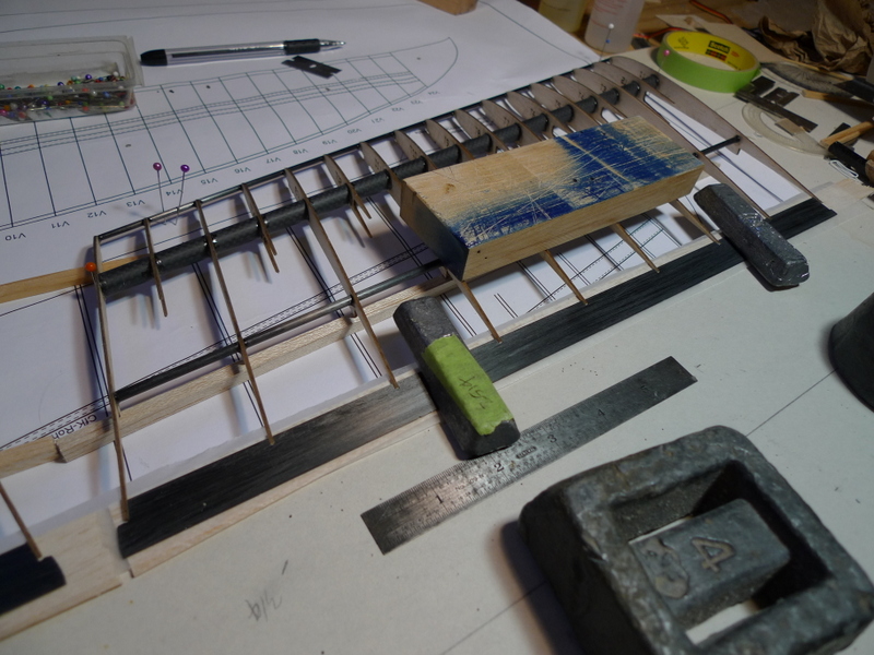
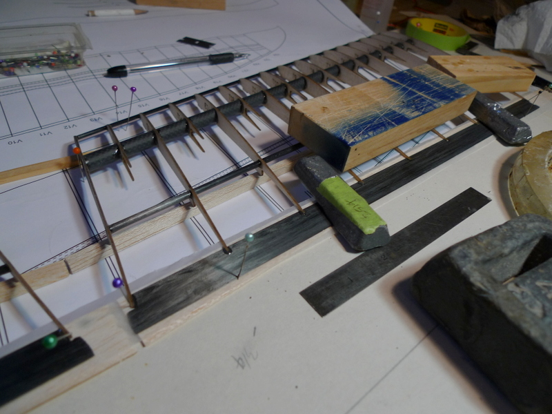
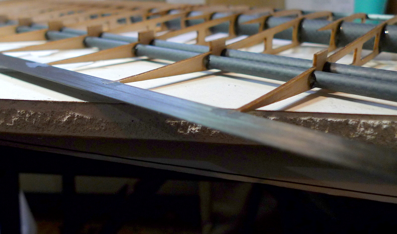
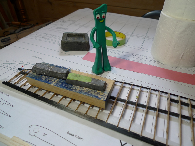
I have glued up a few pieces of balsa to a CF tube.
At rear I used something called Lepages 100% glue, in a red bottle, it stays soft well after three days. Seems plieable, and If pushed hard enough nearest the tube the balsa wood move and the glue appears to want to shear
Nearer I use JB weld, it’s black, and not so nice If you don’t get a clean fillet. I like to use JB weld for CF push rod end to threaded link glue joints.
The two nearest glue joints are with Laminating resin
The nearest I use a baby powder filler to give it some viscosity to hold a fillet shape, and the 2nd one in from the front has shredded FG strands added.
With the shredded FG strands a little more care needs to be taken to create a uniform fillet as some strands get hooked on my fillet tool.


Perhaps Carbon fiber LE D box sheeting
. 5 mm thick
Bonding CF to Balsa
Thinking either


Nov 19

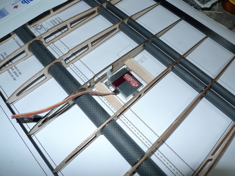
Center panel ribs flap servo can be accommodated in ply rib, linkage exits thru top to actuate flap

center of center panel, rear 20 mm CF tube passes thru 1st three ribs either side of mid point, forward 20 mm tube full length.
plywood rib for left flap servo

left end of center panel , plywood cap rib , two pins from mid panel fit into tubes insert into for and aft tubes in center panel
mid panel left side with half ribs, no d tube sheeting on this panel

half ribs

root end of mid panel showing 2nd rib which can be fitted with aileron servo No hole in root rib for servo wire rectangular slot in servo rib to suite servo connector
tip panel with ribs and half ribs Should consider whether this panel is removable from mid panel or not?
tip panel full ribs
tip panel half ribs
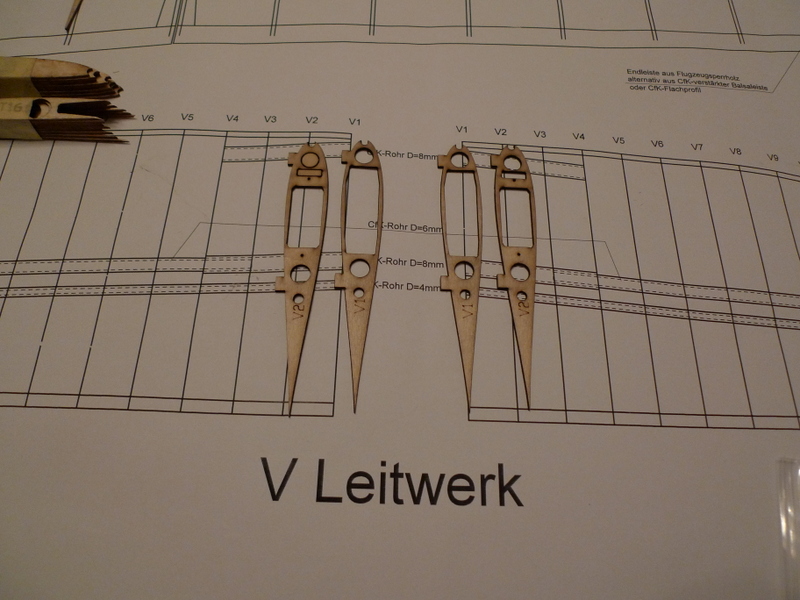
V – tail panels, have plywood rib on each surface for servos
Nov 21
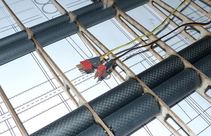
Servo wiring to aileron and flap servos
Two 4 pin deans connector can be used , coming out from the underside of the wings at the center, they could connect to corresponding halves which transition to two 3 conductor wires onto servo connectors that go into the receiver
or a multiplex 6 pin connector could be used rather then the 2 4 pin connectors
As well the ends in the underside of the wing could be glued in place, the corresponding leads from the fuselage would be loose flying leads, one exiting at left the other from the right to keep
The 4 pin deans appear to be a little easier to grab on to.
at the center panel too tip panel join a 3 pin deans could be used, or the standard servo plugs.
The female pin part in the tip can be glued in place, and the other side a flying lead. For the servo plugs the connector pin viseble side would be up when connecting to have proper orientation. the 3 pin deans are not symetrical
In the 4 servo bays there will also be a plug connection , typical servo connectors, harness end glued into a rib slot.
Some cut the servo connectors of and solder to the harness here.
Not a fan myself of this as replacement involves soldering, which is difficult for some and perhaps a challenge at the field
another option for the center panel to fuselage connector could be DB9


Nov 29
A little down time since I was last here, other Projects got in the way.
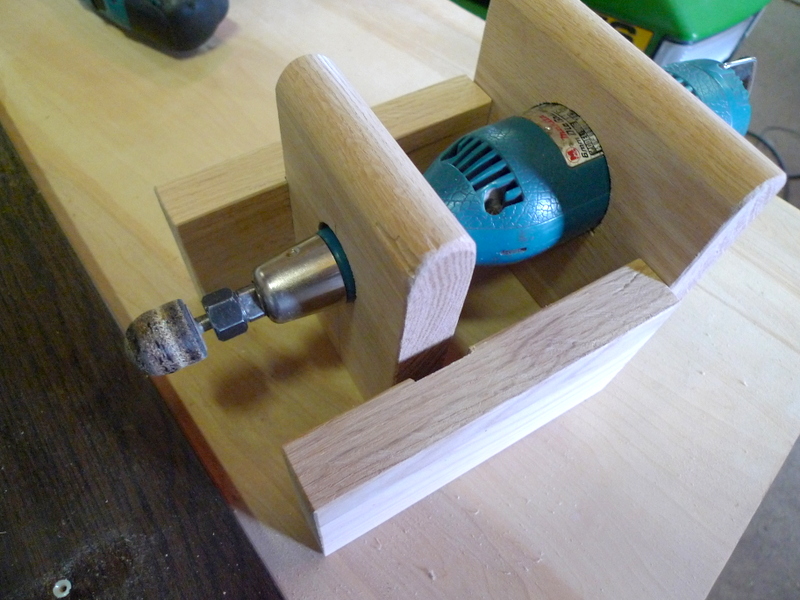
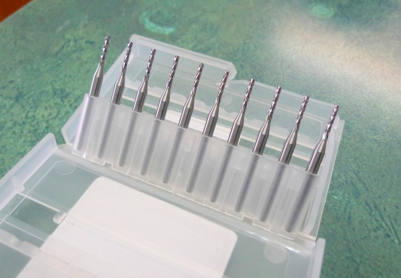
Need to build something to finish CF trailing edges and rib CF sheet to something thinner then I can buy. I have a die grinder with a 1/4 collett, and a 1/8″ collet I fashioned some years ago.
The bits are available in 10 packs from China, 1/8 inch shank, and various cut diameters. Will use 1,1.5 and 2 mm diameter bits


Going to split these two pieces later and they will clamp the die grinder to the jig
Have added a couple side pieces to secure this to the underside of a table

Before I cut this I will drill a couple holes thru for two bolts to clamp the two parts together later
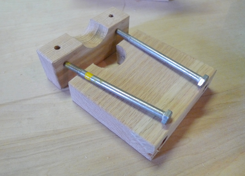
OK, drilled the holes thru, counterbored the head side to recess the bolt head inside the clamp and cut the clamp thru the hole where the die grinder sits

I have everything mounted under a thick table, still have to align the hole and the clamp a little

the bits I have are older dental bits, the shank is under .1 inch but it works and I was able to route a nice 1/16 wide groove

1/16 sheet set in groove, lots of potential with this. I have to track down a collet adapter or make one to get from the 1/4 in the die grinder to the 1/8 needed for the bits enroute
Dec 01
Requirements for Ultracote
for the colors just replace the transparent red with trans blue. So the center panel and stab would be blue – the rest as shown: trans violet, trans yellow.
Vertical Fin Violet

Dec 15
Yes, believe it or not the CF tube is enroute today from China, Tracking says it’s presently in Anchorage AK.
Should be nice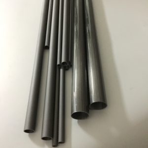

Been working toward some formers as well for the fuselage
Dec 19
Just 6 days after shipping from China the CF tubing is here.
What a great job as well , beautiful tail boom and the main spar fit exactly to the hole in one of the ribs. I was impressed, the only hiccup being that the suppliers representative was perhaps a little eager to say yes, and since I have had to get the 3 and 4 mm tube elsewhere


Dec 20
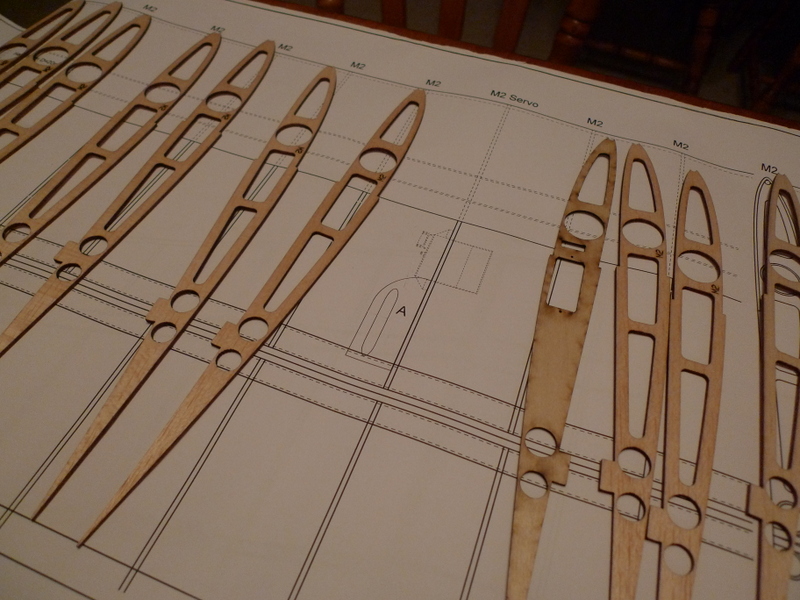
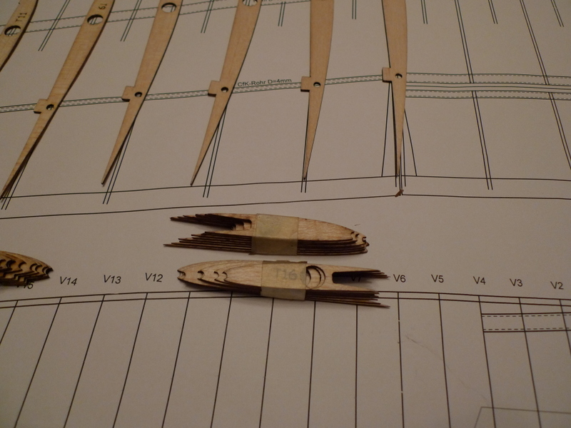
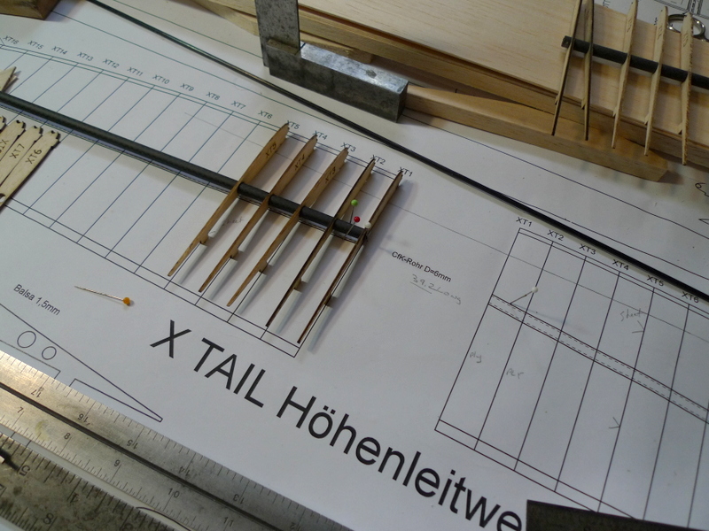
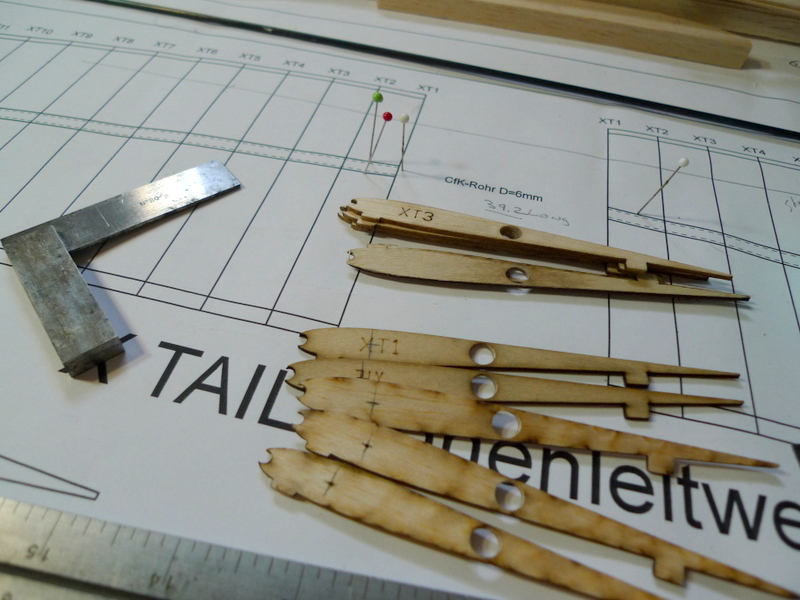
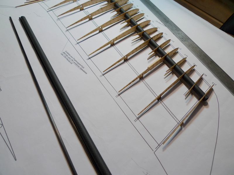
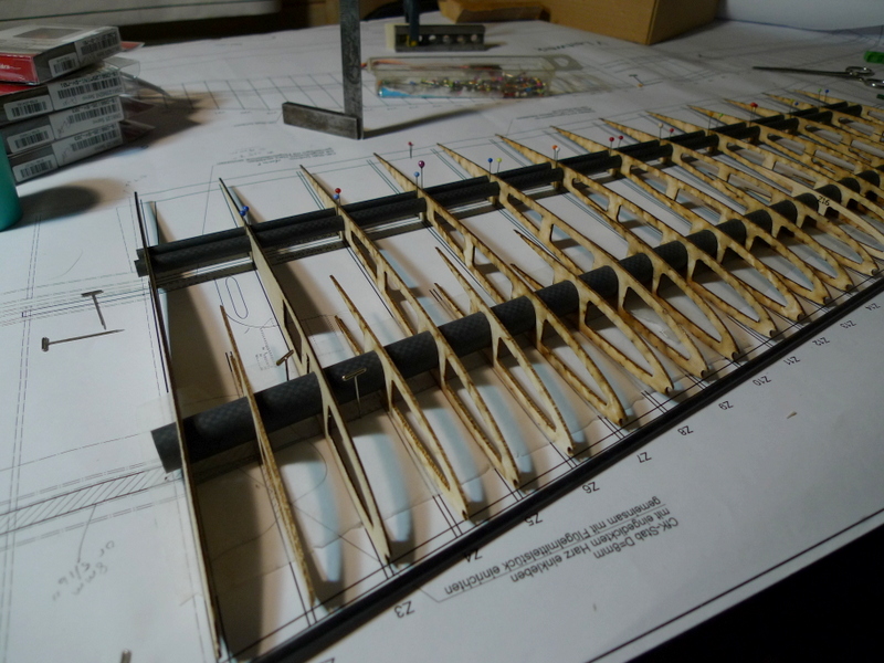
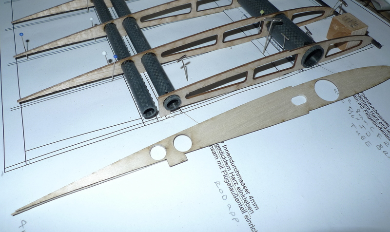
well here you have it the assembly process begins, staring with the stab set. I have to clean up the 6mm hole in all the ribs a bit and skew as well as the ribs are not 90 Degrees to the spar when this goes together. Ribs 17 and 18 appear a little long as well. Not a big deal I can clean them up later
I have contacted supplier , at least they know, and perhaps will clean up their files and re burn and send a couple, or I won’t wait and work with what I have.
I also cut the 6 and 8 mm tube , the two longer pieces for the vertical stab and cleaned up those 6 and 8 mm holes in the ribs as well.
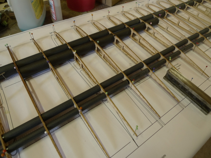
This is not conventional 1970’s balsa sailplane building, 🙂 everything gets threaded onto CF tubes and then gets lined up to the plans. I will use some med CA at all the Cf to balsa joints.


Feb 02
Still waiting for 3mm CF tube
Did receive some end mills though for cutting the trailing edges
Feb 20
Wow it’s been a while since I have been at this, getting the 3 mm CF tube for a lot of the surface leading edges has been a real challenge. One ebay merchant sent the wrong items, 4 speed controls this after an almost 8 week wait 🙂
Resorted to a British supplier and finally received the tube from them. I suppose I could have started without the 3 mm tube, but thought it best to have this beforehand as all the pieces tie together and who knows what physical constraints I will face with the unknown properties of all these Carbon fiber pieces that fit around and thru various sets of ribs.
Well here we go 🙂

The LE of the rudder is 6mm and the TE of the stab is 8 mm. There’s a 8 mm tube forward on the fin that will engage into a 6 mm solid pin affixed to the top of the boom. I will also extend the aft 8 mm tube to engage into a 1/2 rd slot on the end of the boom. One or two 4 – 40 screws and blind nuts will secure the fin to the boom. This should work as far as the mechanics go.
The ribs are not placed at 90 Degrees to the spars so all the holes 6 and 8 mm where carefully elongated with a file/ sandpaper so that they will conform to this geometry. I will scuff the surfaces of all the tubes, and clean with a mild cleaner for gluing.
The Leading Edge 3 mm tube rotates thru quite an arc hopefully the ribs will hold this tension after the entire assembly is glued together.
The Trailing edge of the rudder is curved and will get cut and sanded to that shape. In order to provide an effective method for gluing this to the ribs I will add slots .
I will use finishing resin and CA to do the gluing between the balsa and the CF tubes
Later this Day

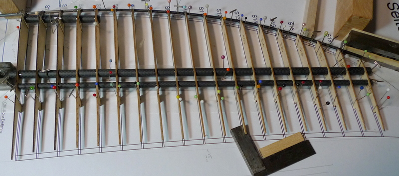
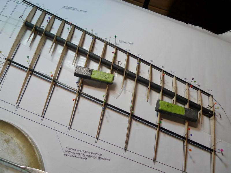
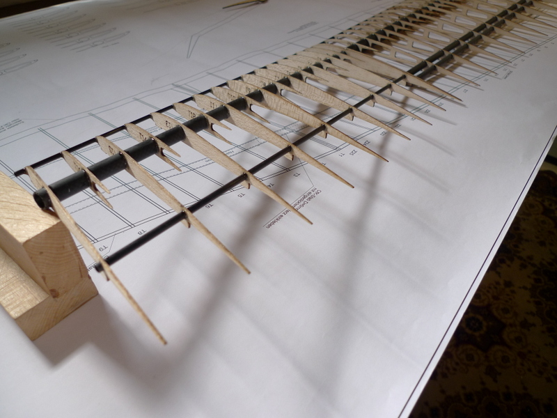
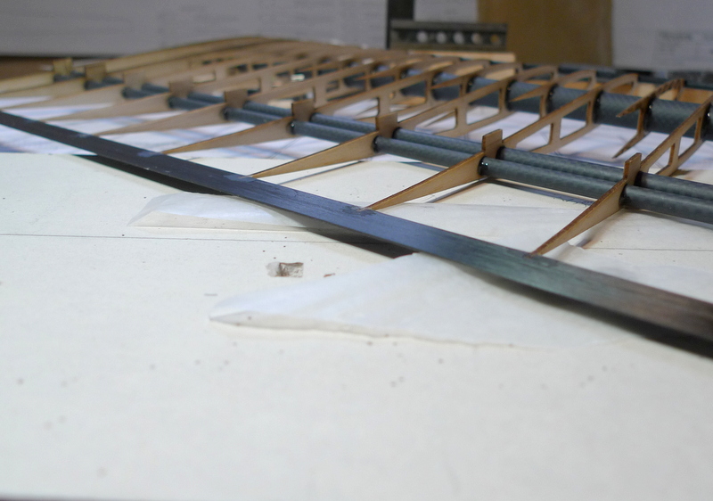
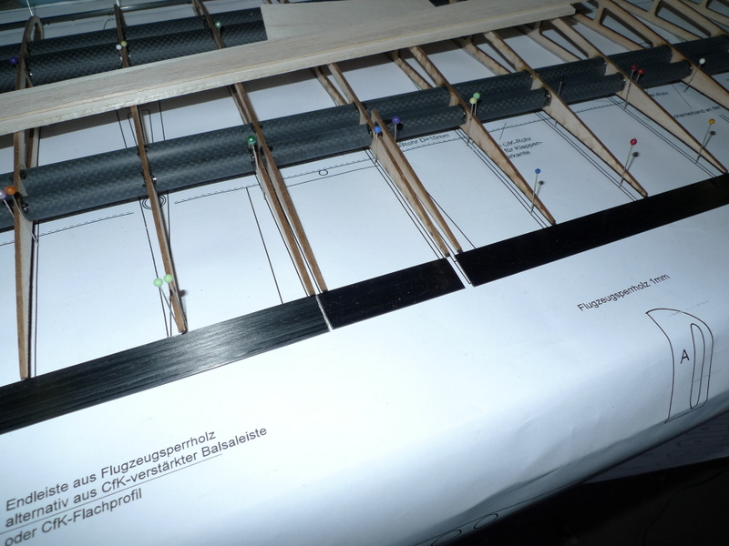
8 mm cf tube aligned, and setting the ribs starting from the bottom
I have a few more located and pinned, this is a fine puzzle

to the top, now to feed in some glue fillets at each tube rib junction

3 mm leading edge, rather stiff but I got it around the corner, well almost . More on that later
Nice,
——————————
Feb 4
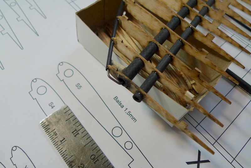
Wing Tips
Wing tip ribs , have ribs and spars 10 mm and 4 mm
Appears I won’t be able to secure the half ribs, until I secure the 3mm leading edge.
The holes need a little cleaning up to suite the tubes, again awesome CF tubes.


Time for some clean up on the fin, well I have added a clip to tie the 3mm LE CF to the 8 MM spar, that 3mm LE is loaded as a result of that bend it goes thru

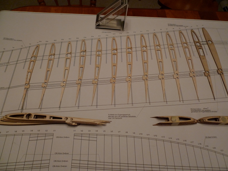
Now onto the Stab, the holes in all the ribs needed to to cleaned out slightly so they could be rotated slightly to suit the angle with the 6 mm spar.
I also chose to add a forward 6 mm spar to reinforce the center of the stab and give another point where to mount a couple hinges or a hinge plate
some 6 mm holes
a final check, and then the spars get scuffed and cleaned for the assembly

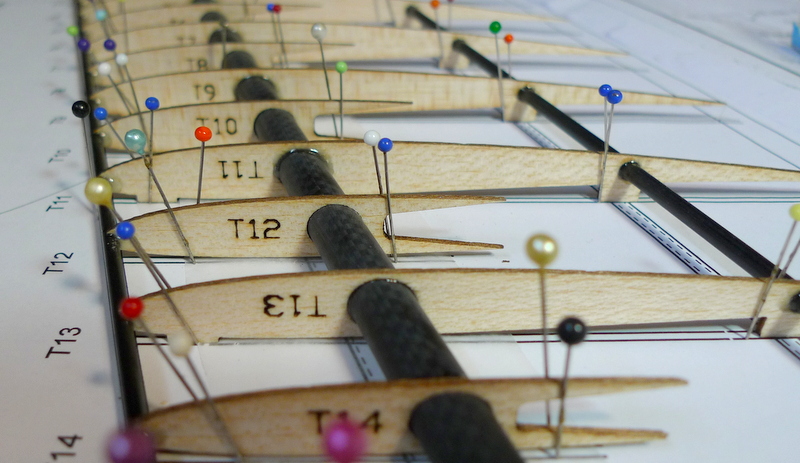
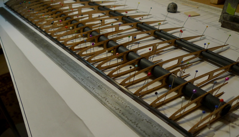
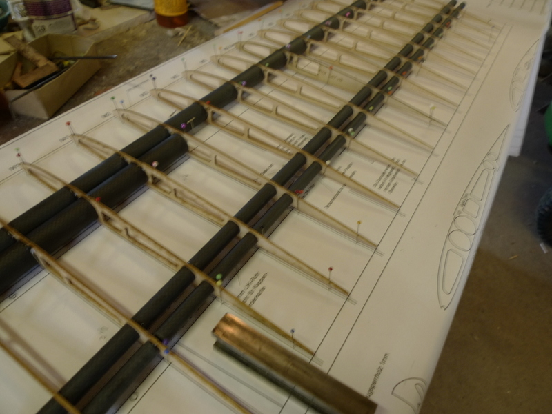
with the spars located to the board the ribs are carefully slid on and individual pinned using 4 pins

All pinned and again finishing resin used to create fillets between the spar and the ribs

Both stab halves removed from the board , they will get joined later then I can add the 3mm LE Tube

Feb 06
Stab 2 makes One

a piece of 3/16 tube fits nicely to align the two spars together

I pulled some tow thru the joiner and will mix a slurry of finishing resin after uuuugh

12 hours later , off the board and ready to move on
Feb 07
Wing Tip Panel Build
I scuffed and cleaned the 10 and 4 mm spars. The tip panels have sub ribs and I will not glue them in place until the alternate main ribs are glued and set.

I like to pre load the ribs making sure all ribs can be placed, and rotated to the correct angle. A little filing here and there is needed so the ribs can be set correctly
The sub spars will get affixed after the main spars are glued and set
all ribs in place aligned and square to the table. The root rib will be glued later at 4 degrees

Now I can place the 3mm leading edge and align the sub ribs
Feb 09

Left tip panel with the LE in place and glued
These half ribs are really fragile at the tips, handle with care

Parts Garage, one at a time.

a mock up with the boom
Feb 10
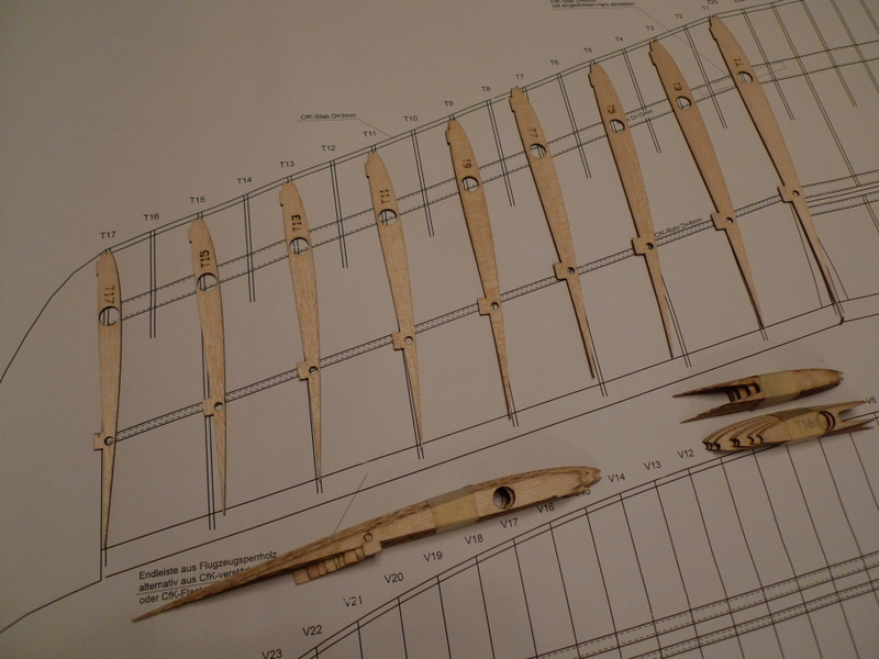
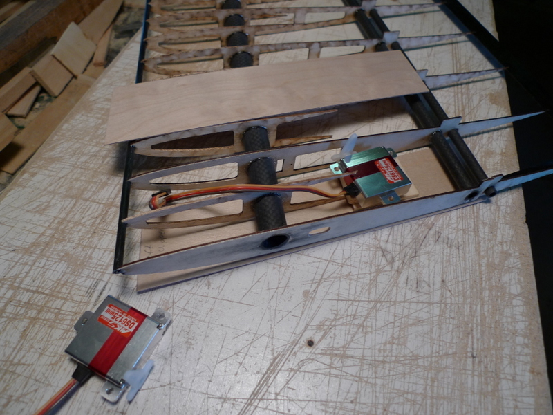
A little tidying of the tip panels then onto the intermediate panels. Flaps, 15mm 8, 6 and 4 mm CF tubes and a servo for the aileron

full ribs and half ribs, 15, 8 and 6 mm holes all need careful filing to accommodate the angle of the tubes

I have cut the CF tubes to the approximate length and will trim them up later

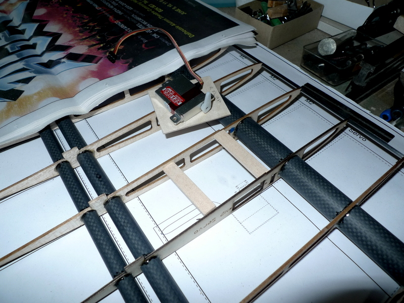
the second rib has a slot to fit a drop in servo, however I didn’t see a good way to get at the screws after to remove the servos, These side mount servos should work nice though

Horn exit from the top or the bottom?
all the ribs set in place, need to be located and pinned though
Inboard end

🙂 the 15 mm tube is not parallel to the 8 and 6 tubes, pushing and pulling without some thought to the order will mean a stash of crumbled wood if care is not taken

I like the servo here and I can feed the lead thru to the root
Feb 12

left intermediate panel

4 pins per rib seemed to have worked
🙂

tip and intermediate panel, need to trim the excess CF tube
8 degrees ? that’s what the plans show, I set the end ribs at 4 degrees

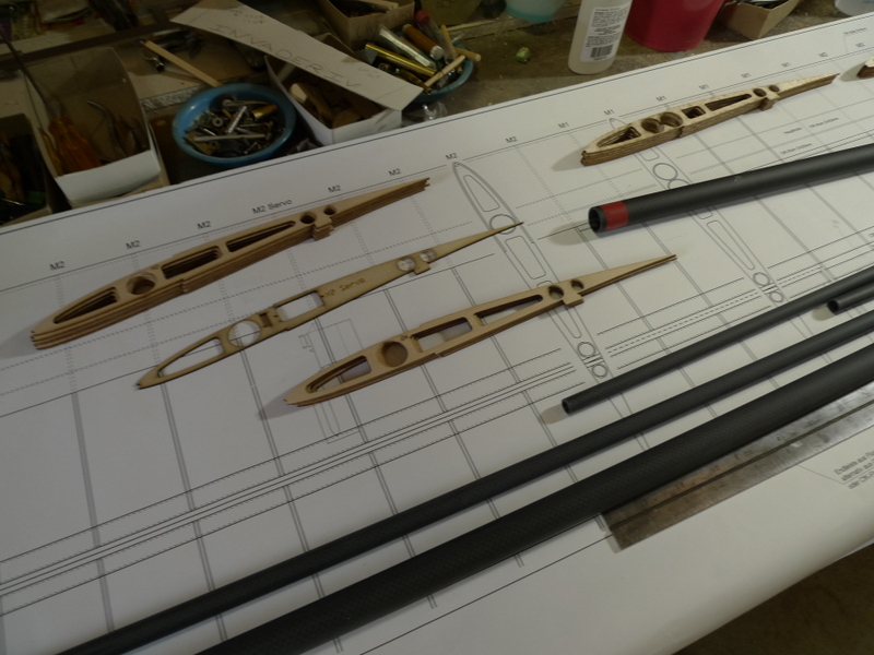
parts for the right intermediate panel
Time to clean up the holes and make sure the tubes slide thru and can be set at the right angle

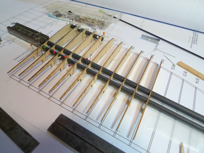
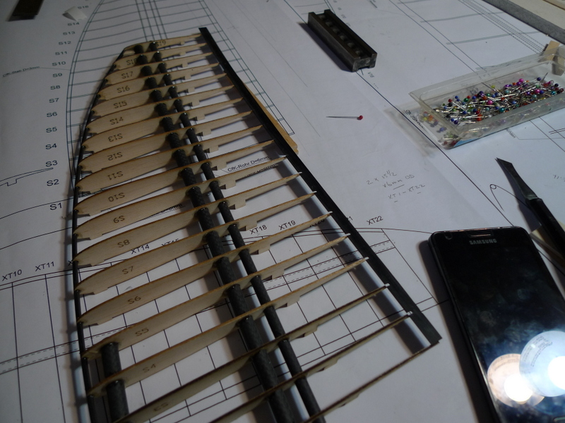
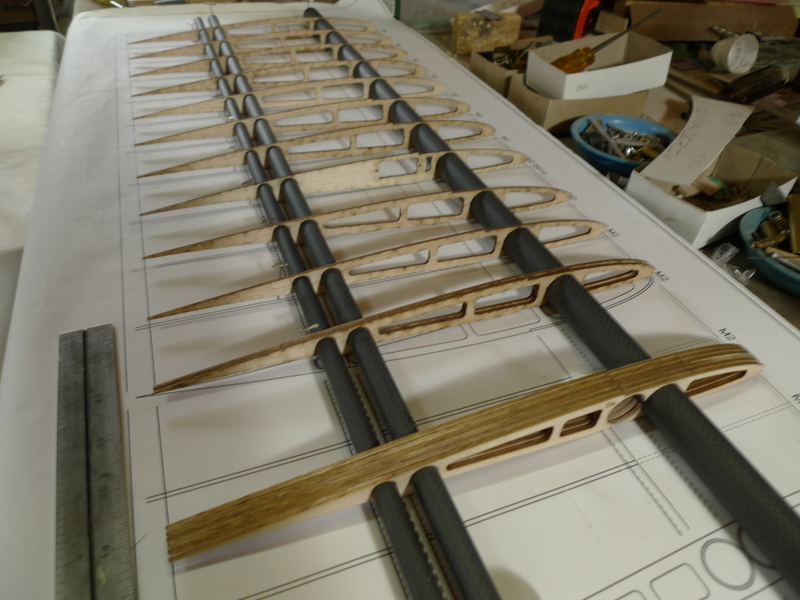
I first get all the ribs placed in order onto the 15 mm tube, taking care not to hook the ends

Then I locate the 15 mm tube to the plans with some t pins

Then I add pins at each of the ribs so I can slide the 8 and 6 mm tubes thru from one end

Final check making sure the ribs are on the right way and in order
Inspector
Feb 13 and this recent News
Hallo Walter!
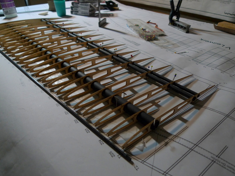
Die Beschreibung zeigt noch ältere Bilder. Die Diagonalstreben sind nicht notwendig, daher wurden sie im Serienmodell entfernt. Das spart auch ein wenig Gewicht.
Richtig ist die Tragfläche ohne Diagonalstreben.
herzliche Grüße
R F
AR-Flugmodelle
Reading thru the German write up
- the ailerons are hinged at the top with tape
- the flaps at the bottom
- the moveable surfaces, rudder, flaps and ailerons are cut from the panels and then the ends of the ribs are sanded so they are flush with the CF tubes
- the main sub spar in the center panel is also referred to as a ballast tube
Feb 15 More thoughts and Observations
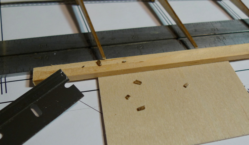
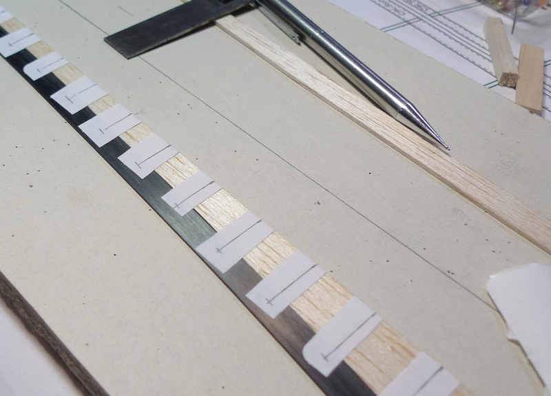
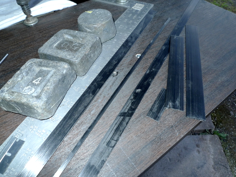
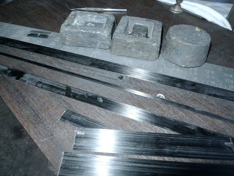
In particular trailing edges a number of months ago the decision was made to use CF sheet for the trailing edges. I believe this is still the best solution and I’m now faced with finding a way to fit CF strips over the end of these thin ribs.
Simply Put
- cut to length
- cut to width
- add notches
- glue in place
- :):)

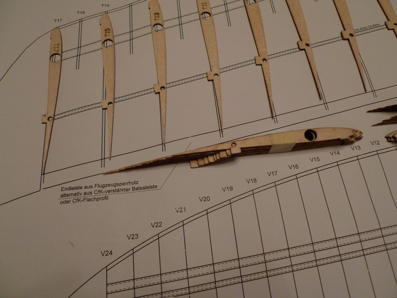
The ribs don’t end in the same plane so I need to move the LE of the trailing edge CF forward and then trim all the other longer ribs such that they end in a straight line and I can notch the CF to suit.

about here perhaps app 1/8 to 3/16 deep notches. After I will need to trim / rip the width of the CF strip to suit.
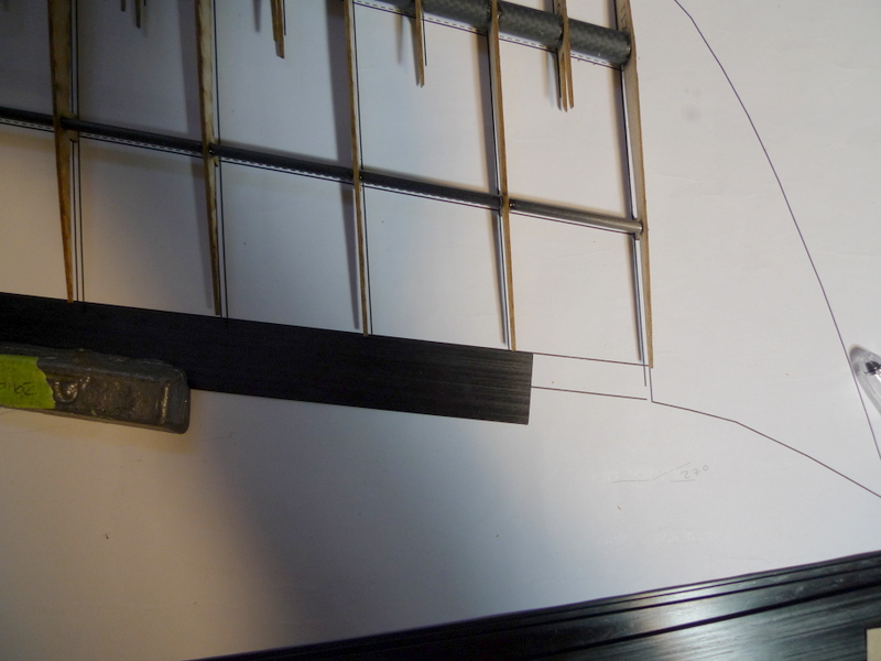
The CF strip is .75 mm app 1/32 thick and as you can see wider then what is shown on the plans

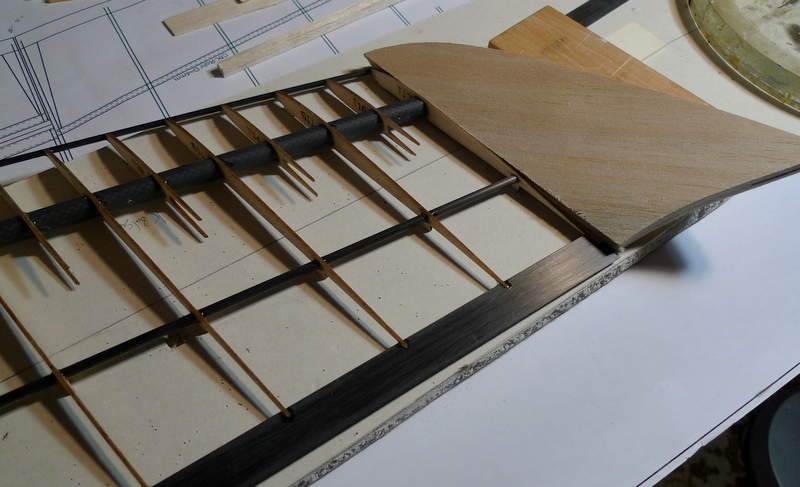
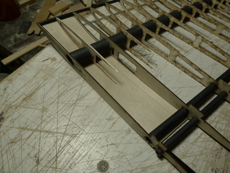
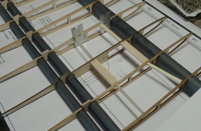
Intermediate panel with the subribs and leading edge tube in place.

Plans showing flap to wing detail with capped ribs up to tube. Ailerons and intermediate panel will also receive this same treatment
Feb 17
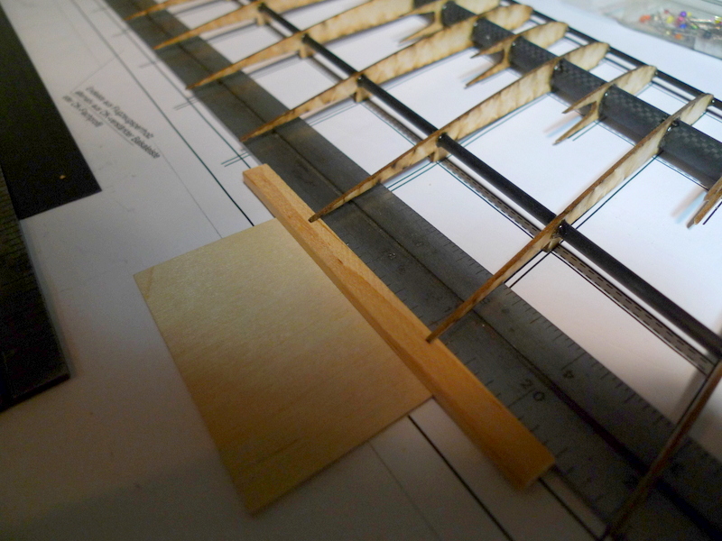
I hope this will do it?
A couple guides and a slide set at 10 degrees, and a stop at the rear of the slide
The aim, get some 1.5 mm notches into the trailing edge to suit the rib tips and get the trailing edges glued on.
I’ll stack the trailing edges for the tip panels and eyeball the location to cut the notches.:)

Feb 19
most of the tips needed to be trimmed, one was shorter then all the rest and I left the two end ribs as they were supplied.
I had to rip the trailing edges to the width per the drawings. That’s all good and later I will perhaps need to do some trimming as I add the intermediate panels
I set both panels up such that the trailing edges lie in the approximate location where I could slide in place the two trailing edges and glue them. This is quite an arbitrary decision though all is good and this will work fine. Some gussets will be added later

This is going to be an interesting wing when it all comes together


Feb 21
More Details, Gussets and Trailing Edges

Aileron root, had to cut the rib and set in for relief in opening

Aileron trailing edge in place

Underside of aileron

Stab trailing edge with balsa sacrificial slot filler
There is an arch in the stab trailing edge, so I added this filler to help with notch cut angle


Feb 23
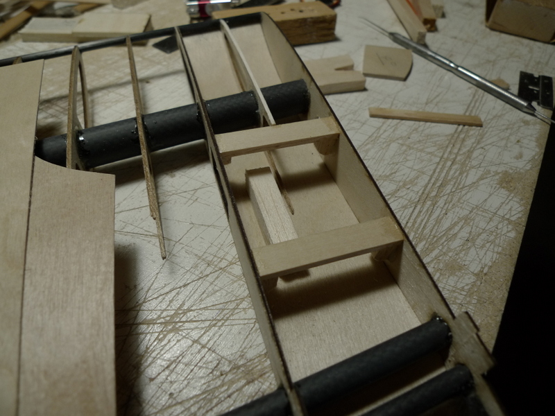
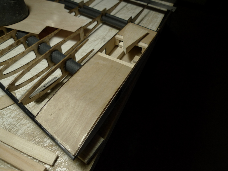
Int. Panel root sheet and aileron servos


Feb 25
Center Panel Build


Feb 27
Center Panel Trailing Edge
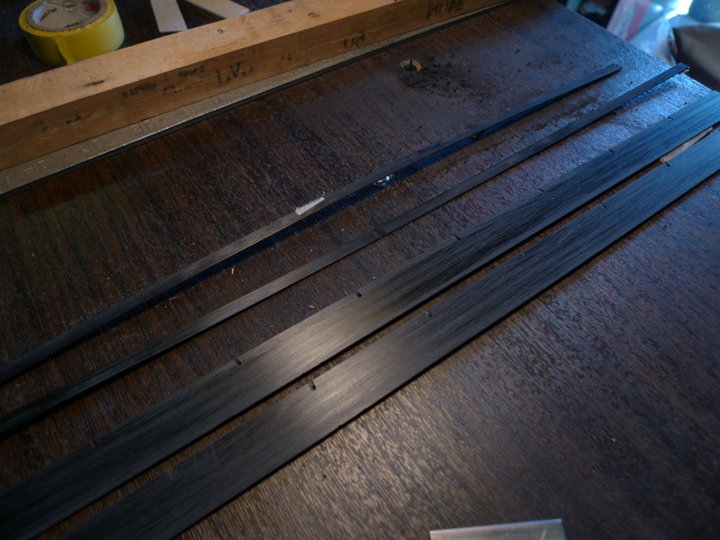
Had to rip the 3 pieces of Trailing edge and then mark and add notches
The roots of the center panel seemed a little light for me , so I doubled them with some 1/16″ balsa
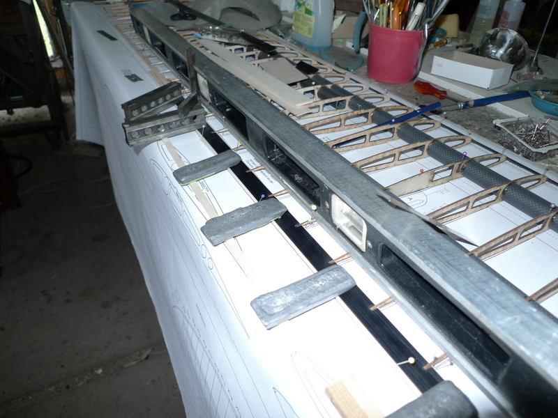
I have set up strips and weights to get the Trailing edge in the right place, when this slow cure epoxy sets I will move to the left side of the center panel and get the TE done there

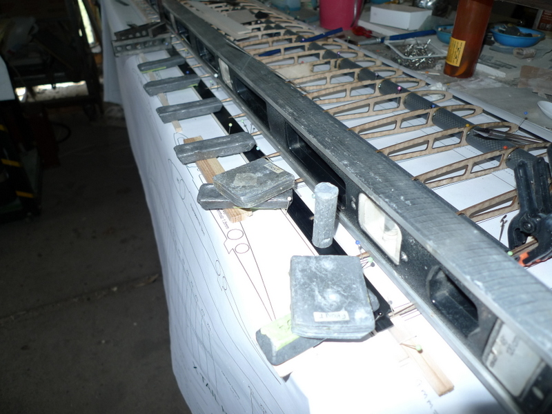
This is not trivial stuff, hope my eyes are keen enough 🙂
Mar 01
Flap Servos, Cabling


Mar 03
There is a Plan in case you were wondering
Welcome Back
The intermediate panel based on calculations need to be up 3.3 inches in order to form a 8 Deg angle with the center Panel. Then of course the root of this panel should be leaning 4 Deg in towards the center panel root at the top.
All good.
I don’t like to glue in the two alignment pins into the intermediate panel. Later they are just in the way. I am going to add a couple brass tubes and use those so the two joiners will be free.
Sure they can get lost, but for fitting later not having them glued in is a bonus.
So welcome back for the ride, all downhill from here , I hope. :):)

These need to be parallel to the board as well as each other or this just isn’t going to work.

Trig says 23.5 hypotenuse, 8 Deg angle H = 3.3 Inch. Of course lets get both sides the same.

Mar 03
It’s been a real nice late winter weather here, but it’s March and one never knows
I did get the outboard large tubes in place on both intermediate panels though, well tacked, I will pot them later once the rearward pin gets place.

a rubber sleeve to locate the inner end of the brass tube, and a cam to locate the root end

This rod and tube are just friction fit for know, until I get it set in the correct location for the intermediate panel sweep as well as polyhedral

another friction fit, in the cf spar is a balsa plug as well so this stuff doesn’t all disappear on me and later it will also stop the glue. Will do that in all 8 tubes

Tip block up 3.3 inch

Matched up right intermediate panel, doing the left at the same time with the jig I have set up

another picture of the right intermediate panel

Short tube tacked in place. Hope I don’t need to remove it
Mar 05

24 Degrees of separation , that’s the angle between the tip and the tip Panel

Right tip panel and tip

I need to add the shape I reckon

My jig , so the other side is the same, some people notice right away when these things are a bit off

Look south from the trailing edge, menacing sailplane

So, back to the intermediate panel join, making progress

a view from the cockpit

Into the root, planning on building one, don’t make this your 1st build, hate to see you get stuck and have to put these pieces into the Chicken Coop while you figure things out 🙂

Lines up as well, whoo hoo

Up next

Pretty
Mar 07

the center panel mated to the two intermediate panels

Aileron cut from tip panel

this saw did the trick

Forming the tips,

24 Degrees it is, the tips are tapered 3 degrees on the underside,

Getting close , who knew they would turn into this 🙂


Mar 09

ailerons as cut from the intermediate panels, I will cut them, and then finish sand the ribs back flush with the CF tube

Ailerons sanded back to 6 Degrees, for down movement later

ailerons jigged, propped up at leading edge to sand

ailerons still require some clean up

1/8 strip on TE of intermediate panels requires significant taper that I have planed of and now some final sanding

Rear cap in place, and held with level.. I like epoxy here

intermediate panel propped up to sand the rear face at 6 degrees. The ailerons are 4 inch wide at the inboard end so they will move significant air

Panel TE

of course the aim is to do one panel identical to the other, so I set my day to make sure that when there’s two of something, they get done at the same time.

Nice. 🙂

I cut the caps 5/8 inch wide, sufficient material to cover the ribs and not worry to much about being flush when I glue the caps on

I’ll get the ends trimmed next and then plane down the width of the TE caps

underside of a panel showing excess cap strip and rib stands that need to be trimmed away


Mar 12 Media Day Coming Up

Build up the TE, prop up the tip panel

Set for tip panel join

the intermediate panels are prepared . The rods where previously set and now get potted,

Some epoxy and then glued together

Nice

Tips next


Mar 15 Mid Month

Left wing panel , tip

left tip panel root and aileron

Leading edge and tip

still need to clean this up though

wow 4″ at the root ailerons huum

Flaps cut out

Have to sand back the rib ends flush to the CF spars

big center panel, 11 3/4 chord

Aha, the fuselage Pod is back, challenge

stab and rudder servos, small but mighty

Side panel templates, going with 1/32 ply and 3/16 balsa, many ways to do this

TE cap right flap side

TE Cap, will clean up later

Flap horn example

sides et al together

side panels rear

1st bulk head, there’s more of these.

Tow hook makes an appearance, working with 1/8 lite ply and 1/16 ply doubler for fuselage pod bottom, will have to see how that works with the tow hook made for FG or CF fuse thickness

this is showing a lot of promise, plenty of room for gear 🙂

Wing saddle, I’ll add some doublers here, as well as some structure to bolt the wing on

Nice , I might add

taking a break, some sour dough rye, 1 KG or so each.
Mar 17 Spring o Spring

spruce for the nose block, 170 plus grams

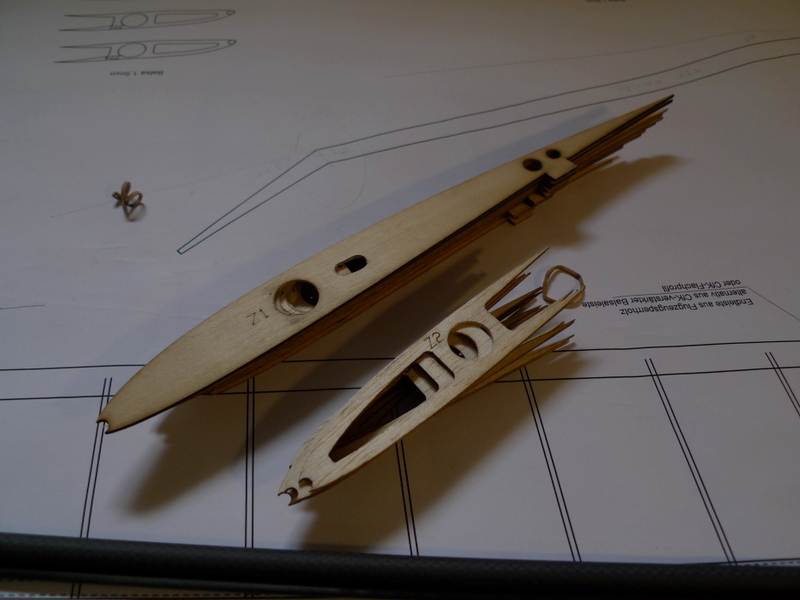
Fuselage formers, 9 pieces when all done

Hollowed out the nose block for some lead later

Mitered corners for fuse fillet

some holes to pass wires thru

Holes for push rods

Promising

Boom, the big end.

side panels laminated and weighted
Mar 19 More Fuselage

out

Tri stock offset to line 1/16 inch


Mar 19 Schwerpunkt
Hallo Walter!
Der Schwerpunkt befindet sich ca. 125 – 130mm hinter der Flügelnase.
herzliche Grüße
Mar 20


Mar21
Colors, white
on the outer aileron panel – with the aileron itself maybe a trans blue or something…..at least one panel will have trans white along with the rudder.
The rest of the plane is now up for decision….
Huum, one panel both sides or 1 panel on one side only 🙂
Mar 22

Canopy Build, 1/4 inch sides, fillets a 3/16 lid and some cross pieces

top filler aft of nose

Canopy sides and cross pieces

I’ll add some notches for the fillets, and later carve this to a shape inside and out

Fillets and sides

cross pieces in place

Next the Lid, I previously added a curve to it to relief some of the tension

an inch short of 6 ft

still need a cap at the rear


Mar 23
Hum, a little hear a little there, seems no one part is complete. Rudder has been separated from the fin, Ribs have been capped at hinge. Focus is on center panel, and how to secure to the fuselage and boom.
Vertical space is key, in the end wings need to be parallel to the stab, and the pinned fin needs to be vertical. No marks or holes yet in the boom.
The fuse pod surely is looking better as it rounds into form

Rear of canopy opening, I’m adding a couple cross pieces of lite ply and later some magnets

One piece horizontal one vertical, will add magnets to the horizontal later


Center panel, harness exit

Not much room in fuse so cavity in wing will store both connectors

1/32 ply over top, and at rear to meet with cf TE

Window on underside of 1/32 plywood


Fin screw and load plate

Fin with 4-40 t nut
23 Pictures of details, stab, fin, rudder, securing boom to wing, tow hook , Huum, did I miss something 


————————–
Mar 24

Stab tips

I’ve added a hole to pick up a stick to tie into the spar

I’ve gotten the shape sanded down close to the last rib profile and will clean things up later

OK, epoxied and ready for more shaping

tip

Line up, I need to add the stab push rod opening and get it lined up with the horn on the stab mount

More tips

and again , nice lines

Fuse, I’m setting up a jig to get the boom aligned with the pod

Pod, cleaned out to fit the boom, I’ll add the tow hook before the boom gets glued in

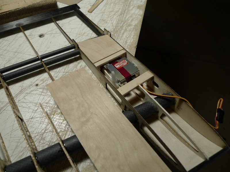
rudder and stab servos, tray and some ply to hold the screws later

Canopy front end as well as eyelet and pin to suit

Servos, clean fit, screws later .. There’s a switch here somewhere as well

Cloth for the bottom of the fuse pod, marked and cut ready to go on

A template is nice to have as an aid to get the radius correct on both sides.

Fiber glass in place

Left wing tip

Tip underside

Aileron servos, for some reason the screws don’t fit thru the holes

Other screws , smaller and longer


Mar 26
Checking my notes I see I first had a look at the Troodon plans last Nov , so I am quite ahead of schedule with getting this bird done.
You may not have know but the Troodon may have been the smartest Dinosaur to ever exist.
No it couldn’t fly but this one will.
I took a moment to assemble it today, and here it is.


 .
.


Mar 27
Boom fuse join and finish . Switch needs a bracket, some thin 1/2 hard aluminum should do it. D-Box sheet.


Mar 28 More Paint and Prep


Mar 30

blue sheets for the flaps

blue flap , purple aileron

🙂

both sets

again

rudder and fin get white

Yes , transparent white lite, If the surface is stiff this is fine, have seen cases though where lite is not strong enough

Left and right

one side

color medley

here’s that Lantern I was talking about, can’t wait to put this all together. Nice color selection

More fin and rudder, hopefully this hinge set up will work, or I am headed back to the workshop

well, no hinges here, must be another set of pictures
April 01
More pictures and some detail on the rudder Build, the rudder should lite up like a Chinese Lantern, brilliant

Ok, here it is the bottom hinge

and the top pivot point, have some concerns now whether or not I can get the rudder in between the two pivots. Would be a real shame to have to take this stuff apart

So, gonna move forward and affix the rudder to the fin, add some spacers, and clamp together

Clamped at the top as well, so I can add and glue the lower bracket / pin assembly

Ok, got some glue slopped into the post and know I’ll hang and wait for 12 hrs

Oops, there’s other stuff to cover

Cut a window for the Stab mount pad here

:):)

Nice

More nice

Tips, an Opaque blue would have looked nice on the tip balsa here. When it’s flying and it will it will be all blue I am sure. Onward and upward, and yes the rudder works after all woo hoo
April 04

Hardware, servos all needed later

line up for push rod and horn install

Find the horn slot, cut away ultracote, and mix some glue

Tip panels inboard section lite white both sides, outer section and tip purple lite

one side white

Both sides white, I’ll cut out access to the aileron servo mount later


April 04 Bonus


April 06 some Blue soon
There’s not much to say as I get to the finishing details, the fuse now has it’s 5th coat of paint. This should be the last brushed on coat next a bit of light sanding and a spray coat.
The aileron surfaces are in place, and have come alive, the cable harness is in use for the ailerons, and that works well. Will have to plant a good portion of it into the center panel, before I cover that.


——————————————–
 :):)
:):)
April 07, some more details, Flaps, flap servos, and blue, and yes the flaps are taped on, they fill a big hole


April 09


April 10 Bits and Pieces
adding the rudder, the center panel is bolted to the wing, the table is level and the wing is level. I’m going to glue the front fin post into the fuse boom, and set the rudder TE square to the table.


April 12


woo hoo, Will it fly, Standby, we shall see 🙂
Troodon SailplaneBuild