3,757 total views, 2 views today
May 18


April 16


April 08

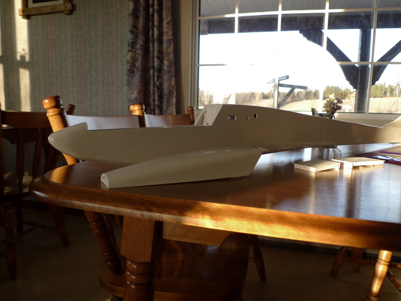
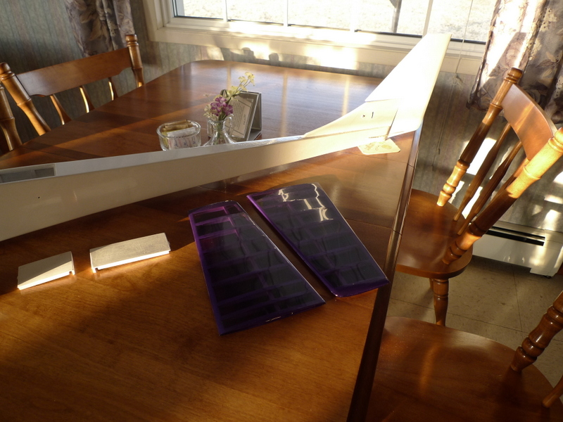
Left and Right

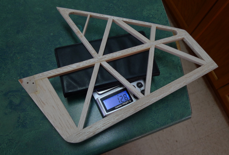
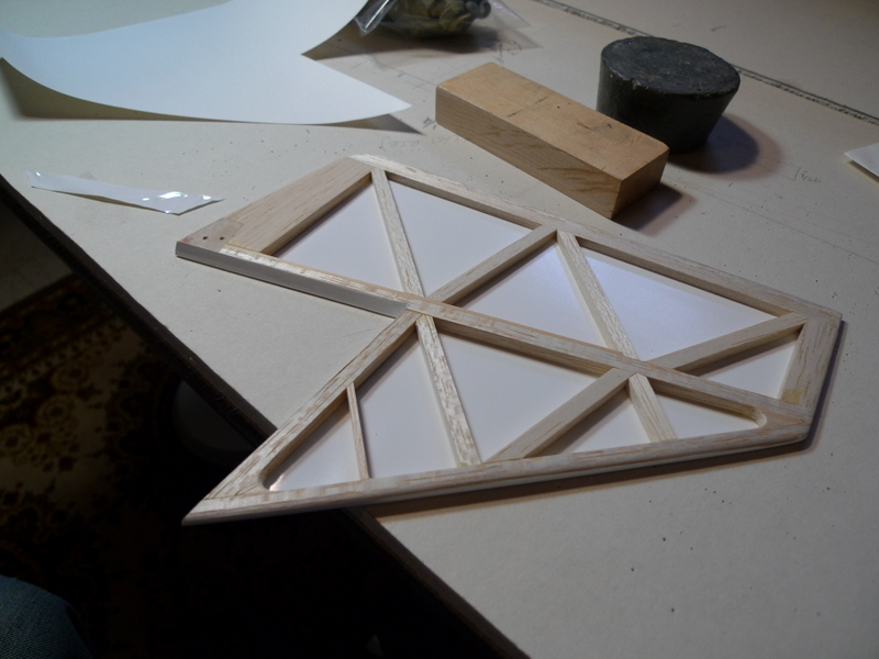

April 07
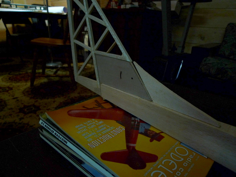
Lead and Lead
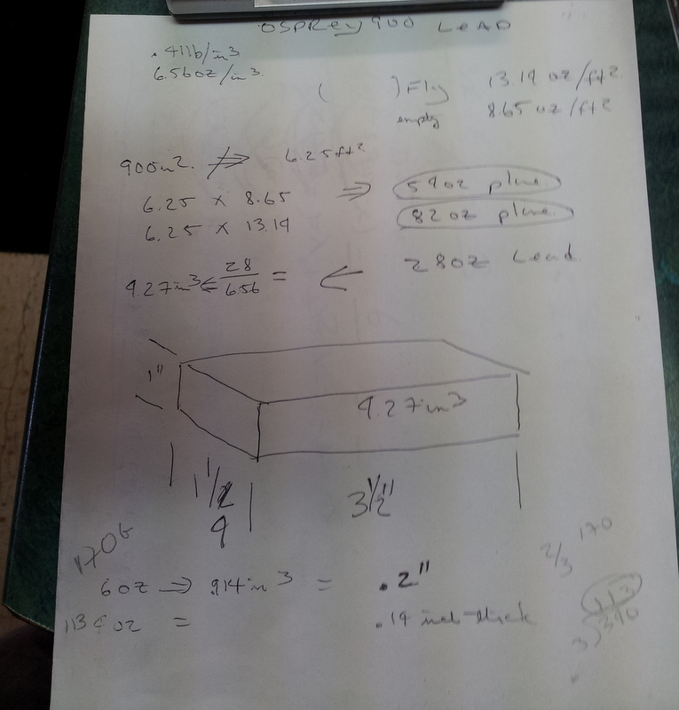

Mar 20 Some Weights
Not covered bare
- wings 560 G
- Flaps 47 G
- Rudder 13 G
- Canopy 27 G
- Rest 568 G
- still need to add battery, 4 lead servo harness, rubber strip, Ultrakote, paint
That totals 1215 G or app 43 OZ
Mar 19
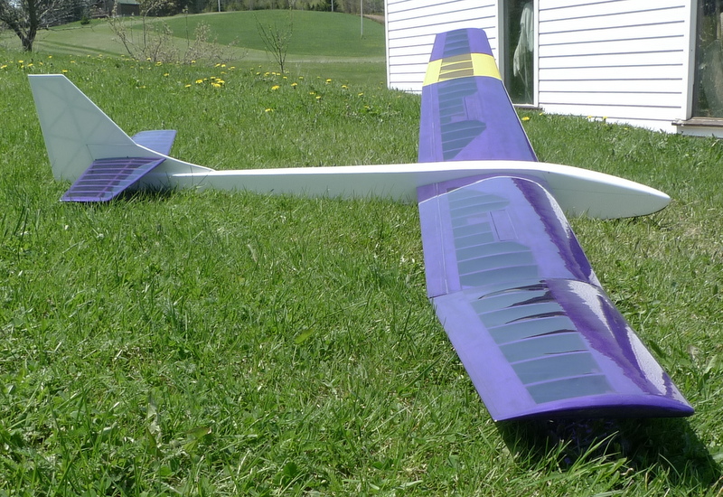
Outdoor Shots
Soon gonna be a wrap on this project. Gonna predict 50 oz or so flying weight at this point, mind you where will it balance perhaps I’ll be a little off?
Still need to cast some Lead ballast, get some painting and covering done.
Gonna be traditional red with a splash of yellow on the wings. Perhaps you wondered, it does throw the eagles of.
🙂
Does this look like a Challenger, certainly not as big


Mar 07
Buttoning up the fuselage underside and adding a tow hook slot and 1/8 ply reinforcement


Feb 28
Wing finishing touches, back to fuselage real soon
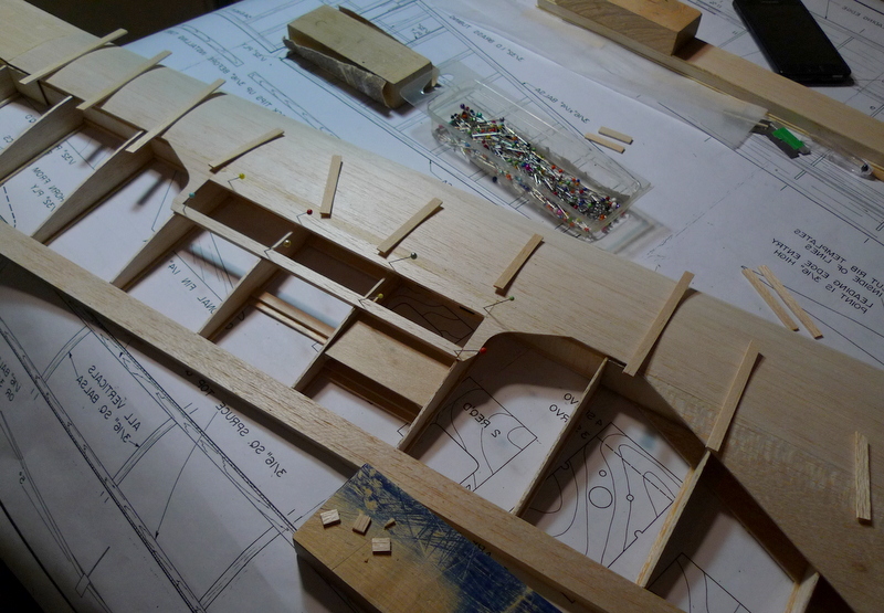
Upper surface cap strips and spoiler opening framing

Flap and trailing edge cap
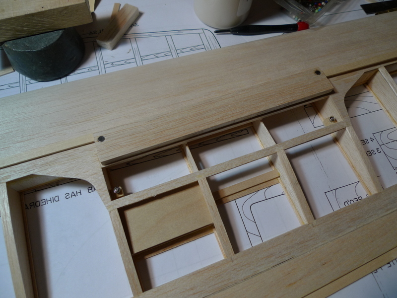
spoiler
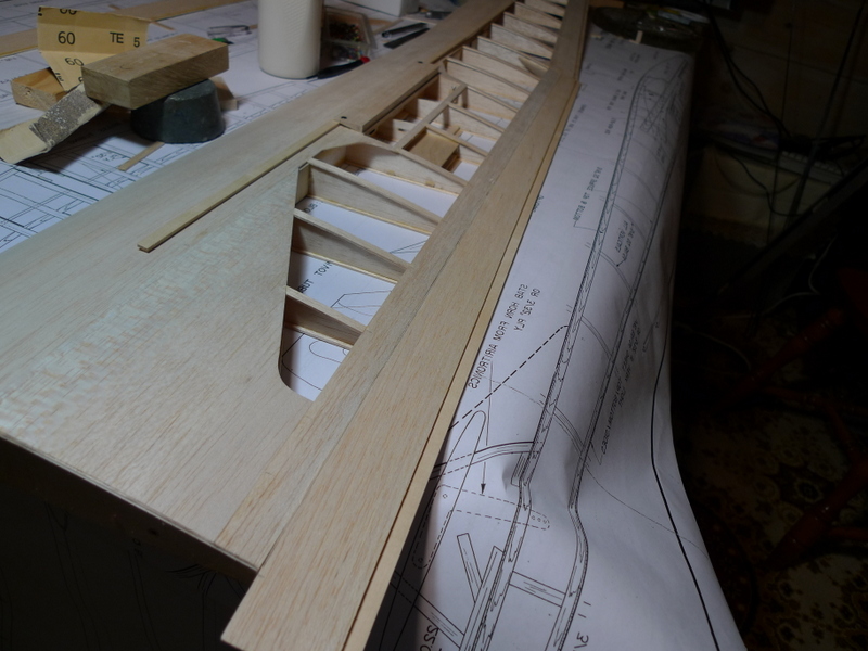
Flap needs some final sanding and cut to length
Feb 26
Wing Pictures

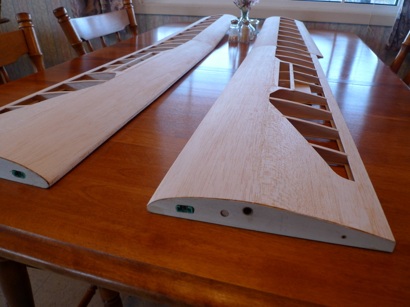
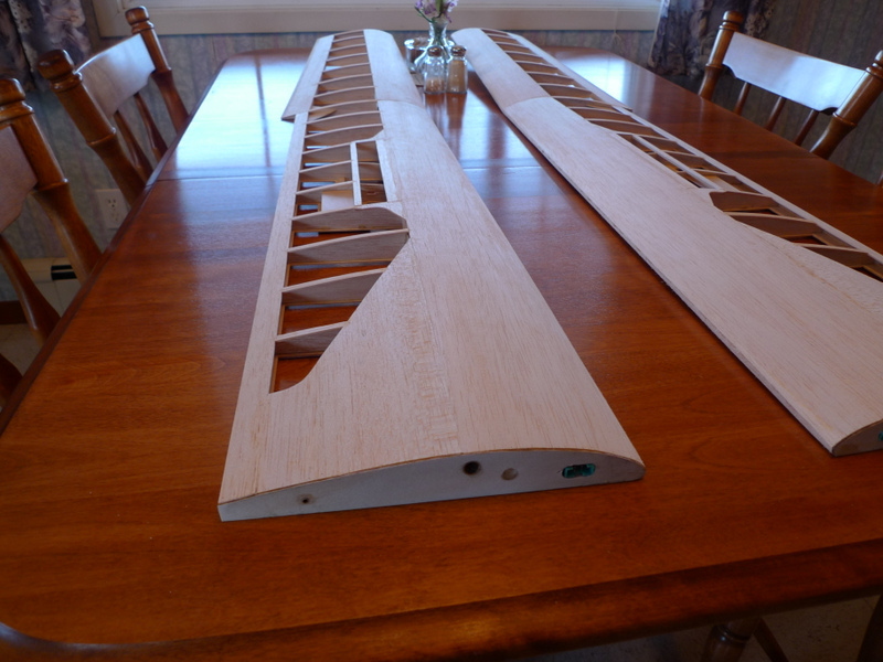
Feb 25
9 Days Later
Working at getting the wings sheeted, and fitting flaps, all takes some time. Before I sheet the wings I wanted to check the incidence as well. If it’s something drastic well, who knows what I will do.

Set the fin on the fuse and tilt the plane (pitch) until I get a level. Stab is set parallel to the fin top sometime later 🙂
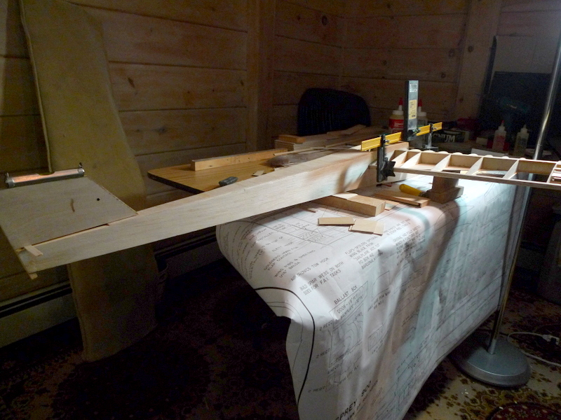
Fuselage blocked, gauge on one wing

another shot right down the right wing

Some parallax issues here with the camera , my eyes say just north of 1 1/2 degrees . That will work

Tips mated to the inner panels. Join ribs and reinforcing still needs to be added

A couple servo lead outboard of 6 pin multiplex connectors

1/16 filler sheet
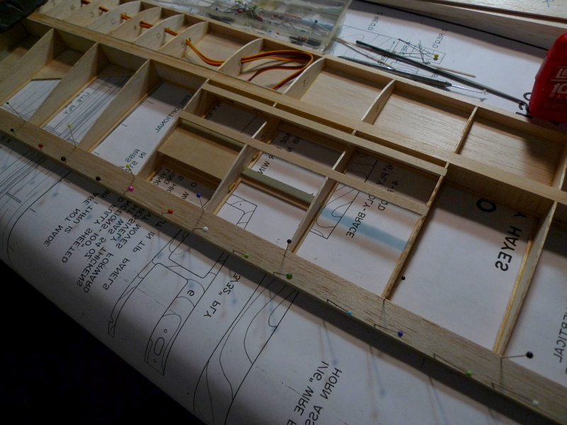
trailing edge sheet
Feb 16
Several Snow Storms Later
The Osprey build continues, cleaning up loose ends and details, before I join the wing panels. The servo cable harness for the wins still needs to be fashioned as it will go in place before I add the top sheeting

Hatch work and frames, need access for adding ballast and removing a wing spring and connectors

Rear access door, sheeted with 1/16 ply

both hatches, I think I’ll secure them with a pin that comes thru from the canopy opening and perhaps a flat blade spring in the wing rod tube box that will force the hatches up at the middle when the pin is removed.

flap spoiler tray

Flap spoiler snuggled in on a nice servo mount
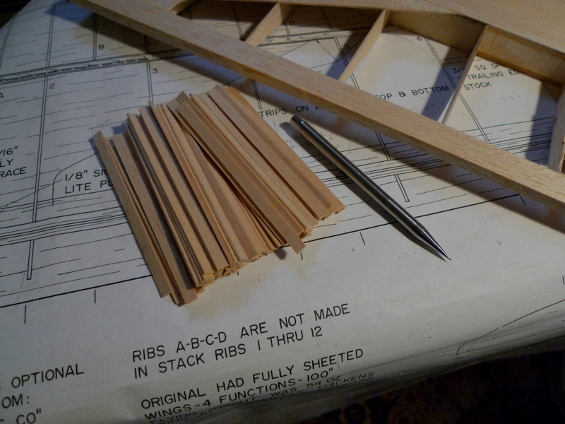
rib caps

More Rib caps
Feb 08
Not so nice outside, strong wind, temperature trending warmer, it’s – 2 at the moment and of course there was some snow over nite so that’s blowing around as well 🙂

Left inboard panel on the board, I have the spar on the lower forawrd sheeting and the rear sheet down as well as the inner end filler sheet in place

I cut the rear cap from 3/16 balsa and it’s 3/8 high to suit the inboard end , later I will shave down the upper edge to taper this to the polyhedral break where the tip panel joins
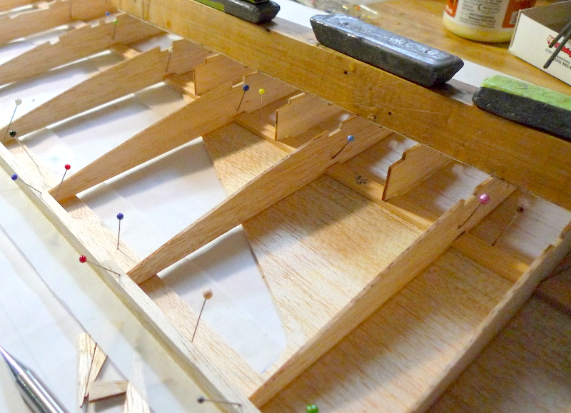
Ribs and partial ribs in place

Notches for spoiler sub spars and clearance for spoilers cut into ribs
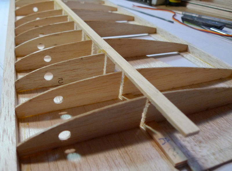
Slits cut for forward 1/16 spar doubler. All the 1/16 ply in this kit is some jazzy wood that is twisted, never seen this before. The 1/16 ply I get from Balsa USA seems a lot more stable without this built up tension that releases when a sheet is cut 🙂

Right tip panel with the 1/16 balsa spar doublers in place
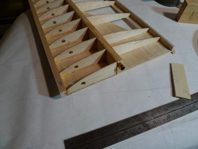
Right inboard root with forward doubler in place

Set up for adding the wing rod tube for the 5 Deg dihedral
Feb 04 2017
Todays Window
Some more of the Wing Build
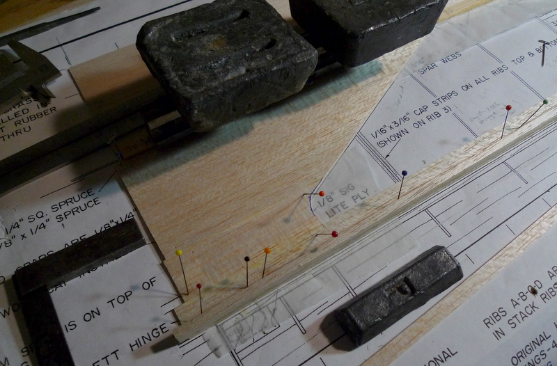
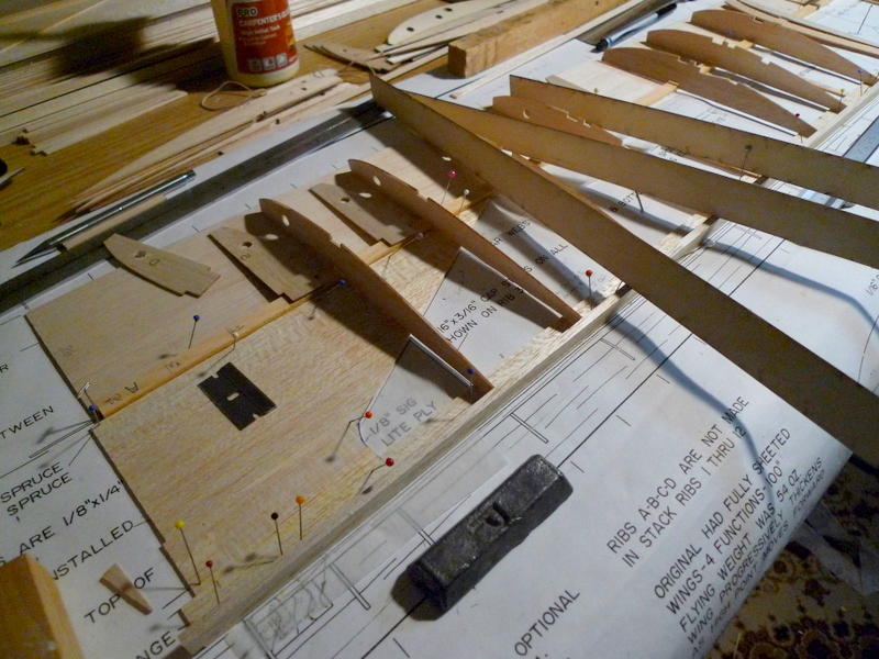
These wings have flaps/ flaperons starting at the root and tapering thinner and narrower as you move out to the polyhedral break. They are drawn as built up but I have chosen to build them out of a solid trailing edge with a spruce cap to get the tip a bit harder. I started by getting the necessary 1/16 sheeting for the lower d box and marking the lower spars for the rib placement. The ribs and spars set on the 1/16 sheet as well as a built up trailing edge. The wing trailing edge at the flap opening gets capped with some 3/16 balsa, which I will taper later to suit the ribs.
The inner panel later will get topped of with more 1/16 sheet and spoilers spanning 3 bays.
The kit arrived with a set of mirror plans to do the left wing, but I have chosen to use these plans and flip them. A couple markers, pin holes will be use on the flip side to set my four foot level. This will give me a straight line to set the spar with lower d box sheet. The spar at the root will rest up against another pin, Since I had previously marked the rib locations on the lower spar I will be all set. The rib location lines on the drawing are then really only used to act as parallel indicators in case where the ribs don’t fall directly over the plans.
The trailing edge sheet 1/16 x 3/4 is placed using a spacer set back from the lower spar. If you look on the plan I have marked the important 3 pin holes with a blue circle so they will be easily found later.
:):)
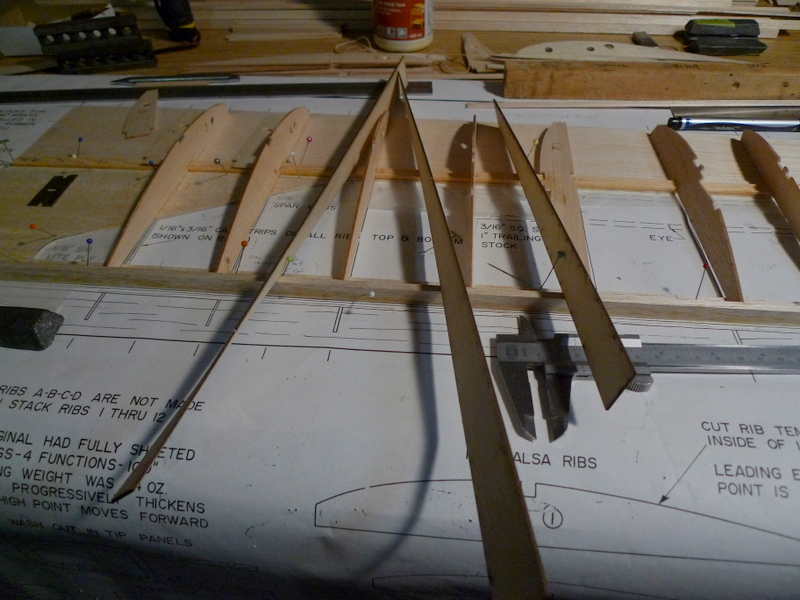
I pre drilled the ribs to allow for the later insertion of servo wire, also added the notches for the spoiler sub spars as well

Jan 3o
More on the Fuselage Build

Nose block lumber

I have added the profile to one piece

Fin frame and rudder

Fin sheet and belcranck extension into fuselage

middle part of fuselage has equal width formers so sides are parallel and I can set these formers square to fuselage sides

a little lead to hold the squares
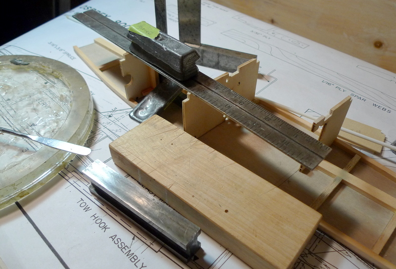
One at a time

a little pre planning to locate the pushrods
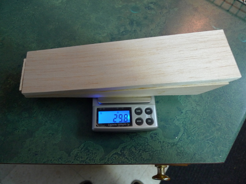
Nose block is fashioned from 3/8 balsa and a spruce frame around the edges
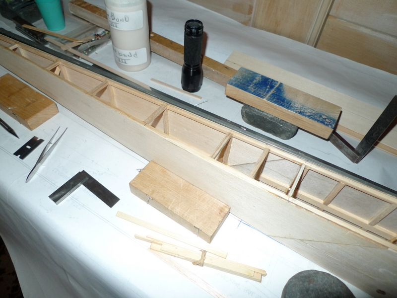
Fuselage 3/16 balsa cross pieces

underside of canopy
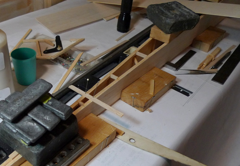
I hold the fuselage square and taper uniform as I add the cross pieces back to the tail one position at a time

Here you can see clearance is needed in the top of the fuselage for the belcranck
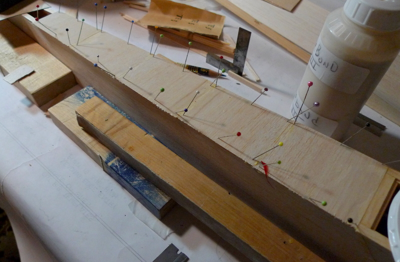
1/16 sheeting added grain 90 Deg to the fuselage


Jan 15
Stab build continues
I am a big fan of symmetry, especially when it comes to wing halves and stab sets. With that in mind I mark spars where ribs go, set spars down straight on a plan set, and make some measurements to locate leading and trailing edges with respect to spars.

spars have been tapered down to 3/16 x 3/16 at the tips and cut to length and marked for the location of the 1/16 x 1/4 ribs. This should help guarantee mirror image stabs

I previously laminated the LE and TE stock with a piece of spruce in the center. the spruce extends inward a 1/16 or so to offer a ledge for gluing the ribs

Leading and Trailing edges as well as spars have been nailed down to the board. I will add the ribs to one side 1st , and then flip over shim the LE and TE 1/16 and then add the ribs on the opposite side. Prefer this over the free form build considering I don’t like to use CA. These copied plans also had a discrepancy in size of one stab with respect to the other.

Progress being made with ribs, I selected some harder material at the inboard ends
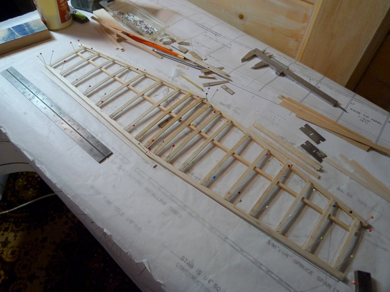
Once the ribs are set and the glue is dry, I flipped the stabs over to add the ribs on the other side

adding ribs to the underside
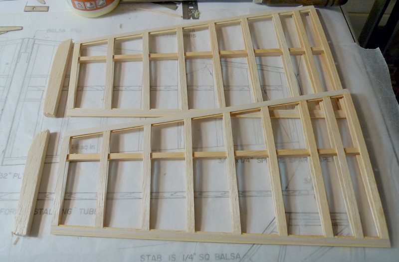
Stabs cleaned up and sanded a little


Jan 13
Fuselage sides, Rudder/ Fin, and parts for the Stab
Take care when working with the sides, the laser cut 1/16 balsa pieces fit together nice, but If I was selecting the wood I would choose something a little heavier / harder for the fuselage.
Would love to understand the criteria for choosing this fuselage side panel 1/16 balsa 🙂

The 3/16 spruce longerons require quite a bend, and I didn’t want to add this preload into them so I pre bent them before gluing

Some water and weight overnight did the trick
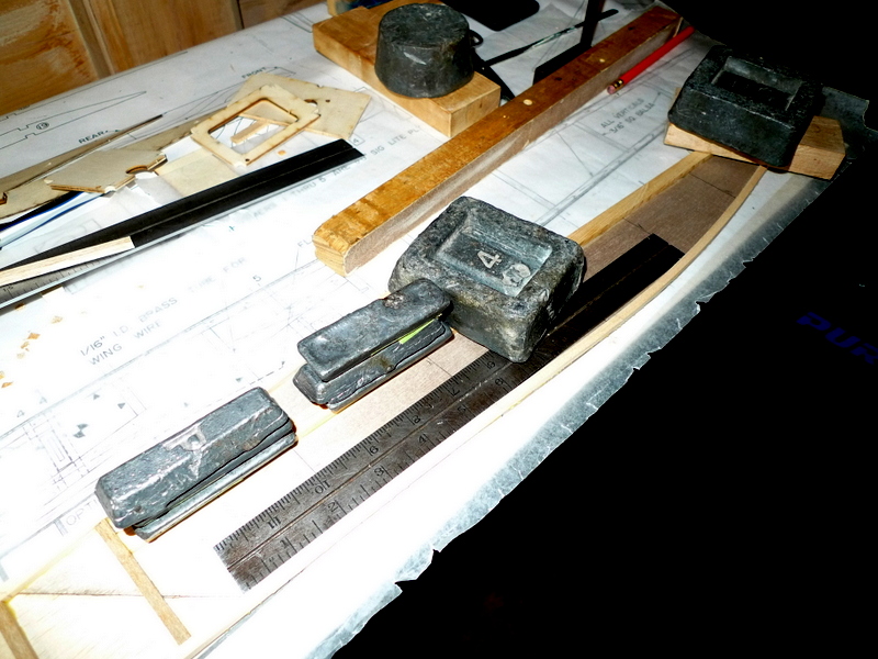
The top 3/16 bottom 3/16 and the 3/16 x 3/8 longeron were added 1st

I marked the cross brace locations on one side and then transferred to the other
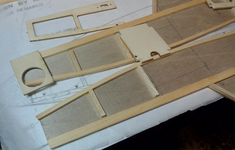
Notches where added to all the formers except the one at the nose block. I added a hole into the front former to access the nose block for lead later

I have decided to box in the wing rod tube here
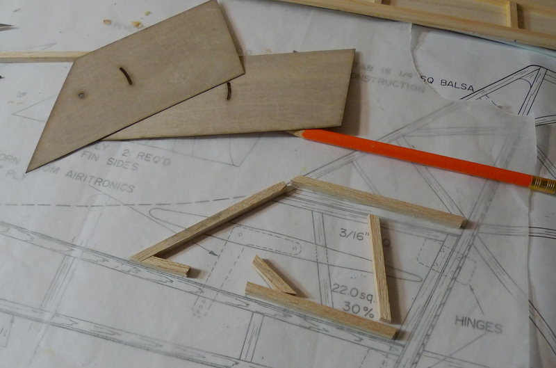
Fin is built from 3/16 balsa and the kit supplied ply sheeting

The fin post is 3/16 sq spruce, I will extend it thru the bottom of the fuselage, and tie in with a wear skid

Rudder built up with 1/4 balsa, and a spruce doubler for the post, a simple stick build

Fin and rudder, I will add the shape later
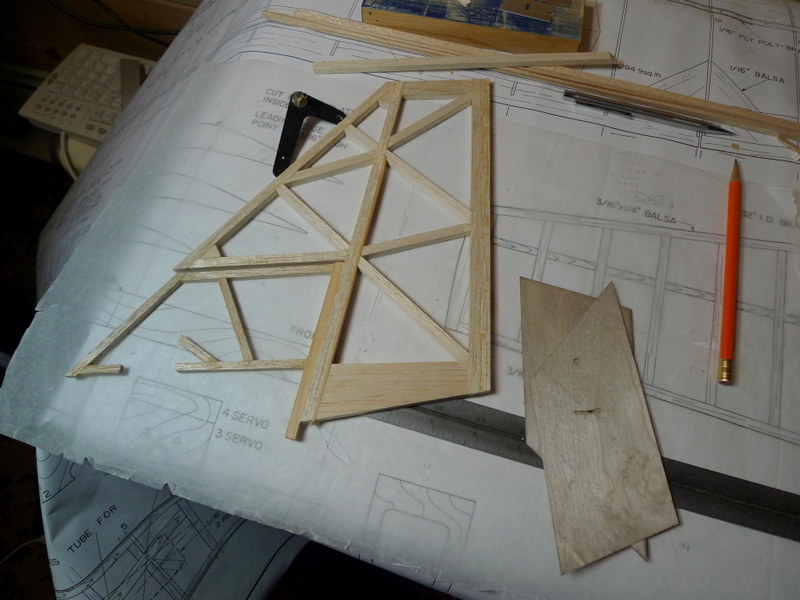
I am using a seperatly sourced belcrank for the stab rather then the supplied ply sheet belcrank
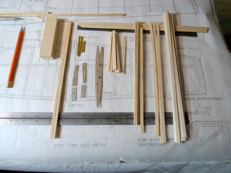
The collection of balsa and spruce I will use for the stab set, the ply is supplied with the kit the rest must be sourced seperately. A note here the inner ply doublers have holes for the brass tubes but they are incorrectly placed as the stabs are built with dihedral
Jan 03
Cutting spruce and assembling side panels
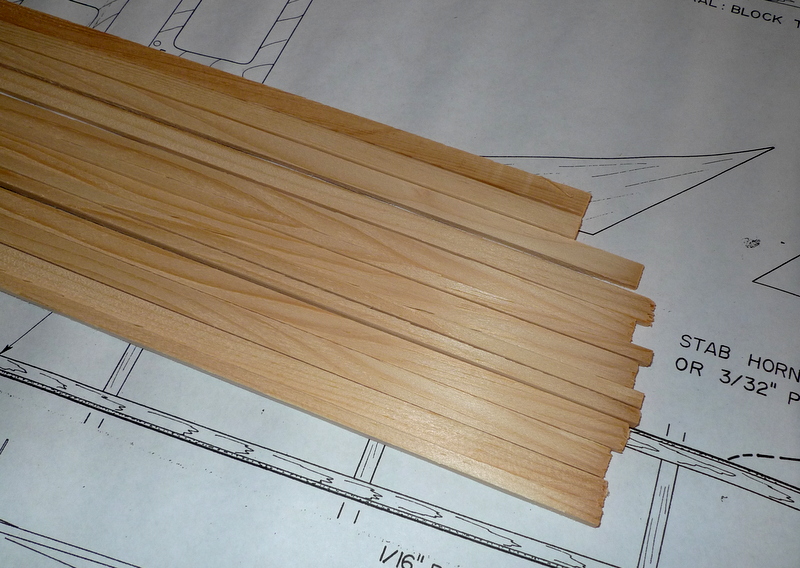
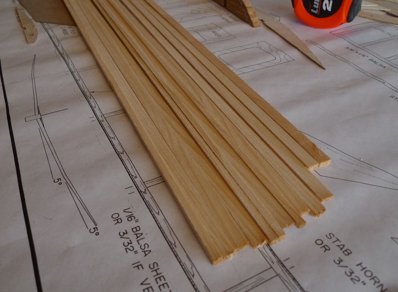
I ripped all the spruce for the spars fuselage longerons and stab spars. There may be a piece that is yet needed but this will cover most of the spruce for the Osprey

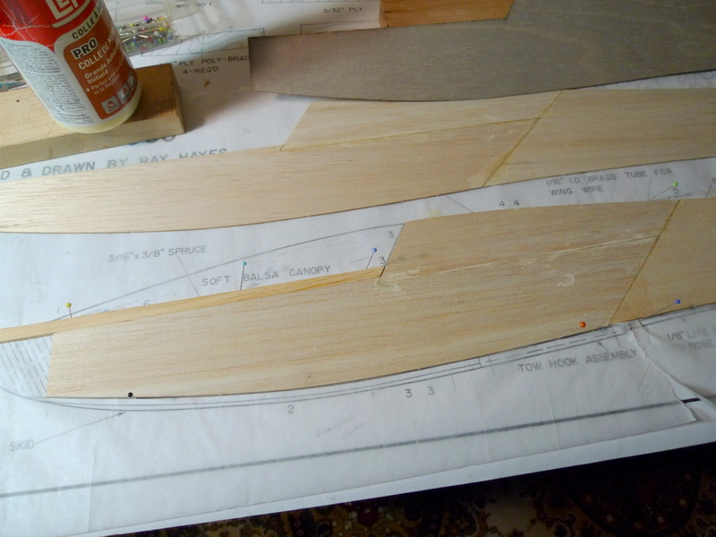
Side panels are put together from 3 light pieces of 1/16 balsa
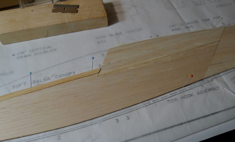
I put in some effort to get one panel like the other and at this point a few pins and a stop is helpful
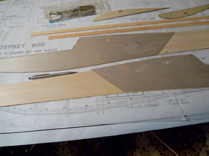
The drawings show a blade type joiner, however the kit is supplied with a 5/16 dia joiner rod. As it turns out the joiner rod tube hole in the root rib is in a different location then the center of the blade joiner on the fuselage side drawing. A Gotcha Moment if your not careful:) I marked and drilled the incidence pin hole and the wing rod tube hole and drilled prior adding the doubler to the fuselage sides

Dec 31

These ribs are done rather nicely.
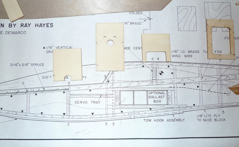
Formers without notches for longerons, I will add them later. Also have noted the wing cap rib when centered at the wing rod is forward into the canopy area by about 1/4 ” Any wood needed for ballast box construction as well as the nose block were not included in the kit.
Dec 19
Had a chance to go over the plans and check some of the cut pieces.
There is some confusion with quantities of Fuselage formers, some are indicated as qty 2 on the plans and only one is included. Perhaps this is a change as a result of removing a blade type wing joiner and replacing it with 5/16 round rod

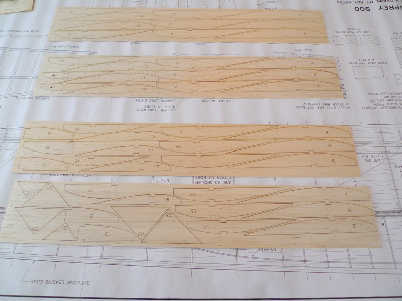
The ribs are nicely done and fell out of the sheets almost too easy, good thing they were shipped with a piece of cardboard and a rubber band, that held everything together nicely

Ribs removed from stack The transition from root ro tip appears nice and uniform in all dimensions. Haven’t yet check the notches top and bottom for 1/8 x 3/8 spars but they appear good. The plans call for 1/4 inch material to build the spars , but that is a chance with this kit as a result of using the 5/16 Inch wing rod tubes, I reckon.
Also did not see any LE detail on the plans, but I like the idea of adding the LE stock shaped to suite the ribs full length and then gluing the top and bottom sheeting down over the LE. Should be strong that way

I have been wondering a bit on how the fuse ties back into the rudder. The rudder is built with 1/4 stock, and the fuse with 3/16 stock and 1/16 sheeting, which makes it 1/2 inch wide when brought together at the tail. The fin tail Post is 3/16 My first thought is to taper the fuse longerons down to 1/16 inch. Perhaps taper everything so I get 3/32 thickness on each loneron, and then sand the side sheet to suit the 1/4 inch rudder.
Dec 17

The Osprey 900 kit is nicely done. The sides are three pieces 1/16 balsa that get doubled at the forward end with a piece of what looks to be 1/32 ply

ply pack also includes what looks to be some doublers for the stab set. The stabs are built with tapered spars and dihedral, which is held in place when the rod tubes are secured

Ribs are cut notched for 1/8 x 3/8 spars and rib 12 appears to be shorter then profile drawn on plan yet seems to suit the plan. Stay tuned.

Fuselage formers and servo tray cut from lite ply I may have to thin some of these formers, those that sit against the ply fuselage doubler.

Dec 15
Nov 15 2016
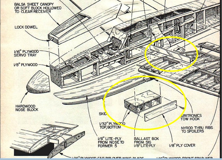
use Ballast box as shown on Dwg, round wing rod, perhaps wing retainer spring If hatch can be added at top of fuselage
d box only with cap strips.
change trailing edges to 1/4 x 1 TE stock perhaps also with TE of
3/32 x 1/4 Spruce
bevel built up flaperon leading edge to get plenty of down travel, hinge on top.
