remove the metal t nuts , actually this kit just had nuts.
ballast tube, a great feature more should consider
round the fuselage edges
clean up the pod to boom transition
remove canopy latch at rear, add magnets
add a slideable tow hook
On to the Build
Unbelievably well done kit, and Documentation, 1st post at top, scroll down for further , most recent Pictures
plywood sheets and balsa sheets, nothing came loose and as I would later discover the tabs holding the ply pieces in where stubborn to cut free , especially where they are at the bottom of some feet on the ribs. Remember these feet are used for the build 🙂Balsa trailing edges were loose at the top
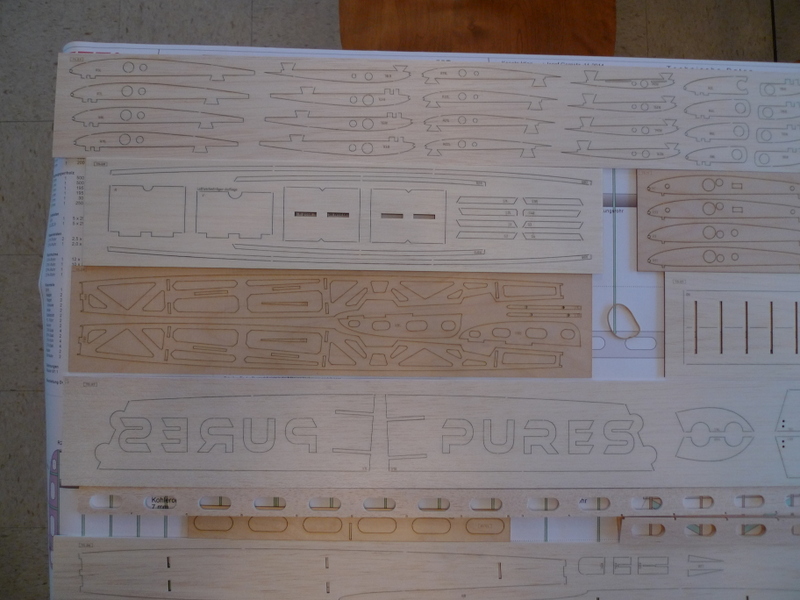
Sorting, and cutting out the Parts
100’s of pieces and pop outs,, the gaps in the balsa where easily cut thru with a single edge razor blade, the plywood required cutting thru from both side.the trailing edges are cut at the ends and notched, one at the center panel and 1 each at the mid panels, the tip panels need the bevel sanded inthe nose block is 4 8mm pieces, I’ll check and see If the LiFe fits into the cutoutthere’s two servo trays included, I will use the one without the cutouts, and mod to suit the KST servosI cut the tip panel spars to length, didn’t see any reference to length, so cut them a little strong, and will trim up latermid panel spars, stronger then tip spars, and cut to lengthsome of the ply in the pod, will clean up the notches and slots before gluing.wing mount cross pieces, and slots they set instab set, they are marked left and right and the tube slots are offset to correspond to the holes in the boomhere you can see the left and right markings, the slots will need to be opened up in the boom to allow the push rod tubes to come thrustab caps cut to fit ply root caps, yes there’s a left and right here as wellstab tubes to long, will cut to length before installcleaned up the ribs at the top, the feet, and the holes where the spars pass thru. The feet are fragile, so take care with them, an particular as some of the thin ply feet, have the retainer notch at the narrow section of the foot(bottom). The cutter would be well served to cut the feet completely and have the sheet retainer notches elsewhere 🙂
I am beginning to imagine a couple color coats on the fuse pod, with some clear sprayed over as a Topcoat
Left over center panel CF tube, may work well as a ballast tube placed here between the two bulkheads, is there clearance for the servos, what about the tow hook and the bolts for the wingstabs with 3 MM cf tube in placeend pieces get added and are cross grainused titebond to glue the end caps in placethe glue smudge should clean up with some sandingtip panel caps are thin ply, I will shape the holes to suit the sweep of the edge later2 mm pushrod sheathing, and wire push rod insidefuselage sides with ply doublerfuselage pieces cleaned up, and glued together, fuse formers will be added once servo tray and ballast tube is configuredthese are the pieces that cross between the fuse sides, as well as the nut that picks up the wing mount bolts.fuse ply doubblers and balsa side panelsthe tube exit slots were cut 1 mm wide, and needed to be opened up, and perhaps get lengthened to suit the 2 mm or so OD pushrods
Fuselage and the Detail
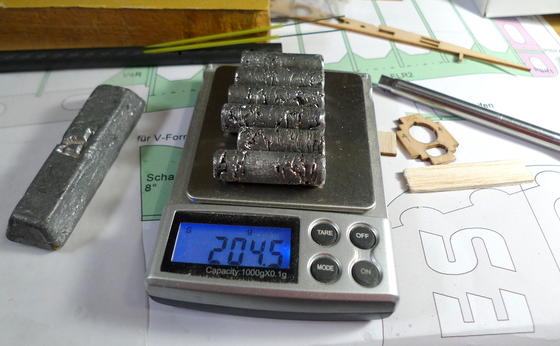
crosspieces and rings, turns out these rings get used in the wings, and the doubblers for crosspieces are elsewherewing hold downs, the doubblers that capture the nuts need to be rotated correctly to provide clearance in the mating slots at the top of the fuse side doubblercorner fillets, arrange flush and glue to the edge of the fuse sidestoe hook arrangement, these are 2.5 mm tow hooks, too much or won’t bend, that is the questionI bent up some tow hooks from 1.5 mm MW, to lite I reckonthe 2.5 mm hookwon’t need all this, decisions decisionskey setupper fuse side doubblers that form the wing saddle, as well as pick up the crosspieces for mounting the wingshatch detail, magnets it the rear will be a good alternative over the slider16 Degree angle tip to mid panel10 degree angle mid panel to center panel.ply doubbler at upper edge wing saddlelooking great, the 4 mm x 4mm balsa fillets in the corners are not cut square, I cleaned them up a bit and then fit them flush with the edges of the balsa fuselage sides.top and bottom fillets in place, up next the ply doublers at the wing saddlesome clamps with backing on the balsa sidethe basic setup with the forward jig when setting the boom to the podaft jig, not notch at base and there’s one on the back side, to align this over a straight lineI remove about a centimeter off the forward end of the boom, need the space for a ballast tube, and yes the tube conforms to the length given on the plansunderside of ballast tube, fits up against aft bulkhead, will be removable in case access to the top side of the tow hook is neededfrom cg back to former I measure 7.3 cm, that gives me 14.6 cm ballast capacity if over the median CG as shown on the plansforward end of tube, I will cut to length, to fit between the bulkheadslead slugsballast tube, and lead CG location shown in blue ink, on lower corner filletyes, the tube will be removable, wire retainer at leading edge perhaps:)
Wing Mid Panel Set UP
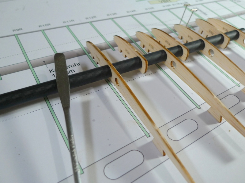
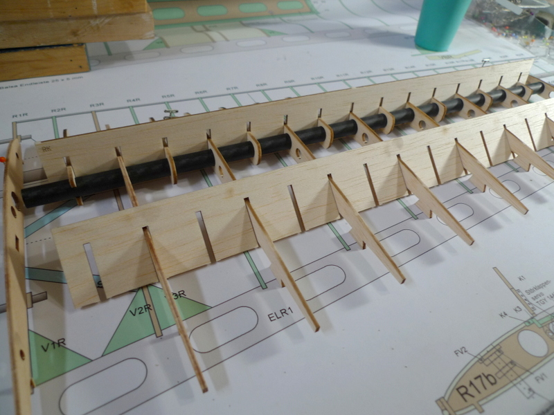
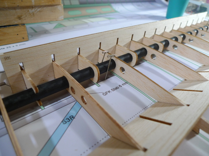
I previously found sorted and cleaned up the left and right mid panel ribsa couple ply ribs are used on the inboard end as they pick up the joiner rodpins are used to accurately locate the CF tubes end to end and fore aftfeet are also cleaned up a bit to clean away the little balsa nib left behind from the sheets i like to lightly scuff, and then wipe the cf tubestake care and set up the ribs, so they get fed onto the tubes correctly, try and push at the center where the holes areonce they are all on focus on spreading them over the length of the tuberight mid panel ribsmore or less in approximate locationthe rib combs work nicely to adjust the pitch between the ribs, though location for the set still needs adjustingthere’s also some dashed guidelines on the plans , parallel to the spar which I will use to locate the combsplacing the 2.5 MM leading edge rod will confirm that all ribs are in ordernice and clean panel, do not glue root ribs until later , as they get set to an angle with the gauges, and care should be taken there as the set of 3 panels for each wing are in a line, and the roots should be set perpendicular to the sparglue the roots in last, and use the correct gaugesi trimmed he base of the gauge, and set it in between the two panelsremember to keep the panels down with some weights as you do your gluing, watch for pins as well so they don’t get under a foot somewhere 🙂I remove both panels off the board in order to remove the feet and fit the trailing edgeboth panels line up nicelyshould be good to gothe trailing edges taper towards the outer end, and must be sanded down to suit the height of the ribs at the aft endset and glued in place, the panel was placed back on the plans, helps to leave the locating pins in from the previous step
some more fuselage, tite squeeze
I removed some material from the two outer nose pieces to get some extra width in the cavity for the batteryjust an option at this point, perhaps I will need some lead as wellan option for the receiver, end plug in seems best, 4 channel surely would get more roomservo mount layout, nice that the blank mount is included in the kitthe forward bulkhead also needed some work to clear the batteryand the top fuse side rails, needed some thinning to squeeze the battery thruJr receiver down in placethis would be another option for receiver placement
Tip Panels
tip panel ribs get laid out in the same fashion as the mid panel, the inner rib will get set at 8 Degrees laterright tip setgetting the ribs in ordertip up against mid panelfeet stash
More Wing, and a mystery
rudder vator caps at the root end, it exactly clear in the documents, but I see some remblence of those in the pictures mid to center panel join, the tubes are glued in first, I set the spars over a straight line and use a jig to confirm the heighta little clean up with a long block at the roots gets a better fitthere’s clearance hear for the larger phillips head screwsthe lower center panel sheet with the access door and the back stop on one sidemid to tip panel join, needs some clean upa block and a shim for height confirmationcenter panel mid ribs, and doublers for spoiler servo screwsspacer at screwlower sheeting 3 pieces, kept the text up, one side so it can be hidden, and the front edge of the opening over the spar. some trimming is needed to fit itcolumn extended to underside of mount for ward m5 screwcleaned up where the sheeting meets the spaces at the LEdiagonal braces at root centers, will surely keep the ultracote tightstops on underside of window will keep the door from falling thruready to be glued in place, find tite bond works good with the plywood ribstools I use for applying medium CA as well as tite bondlower center sheeting glued and weightedjig for sitting panel angle heights, this will make one the same as the other. a little math worked well for the heightsone side tip panel the other for the mid, try to place then square in a couple planes as welladding gussets, not flat to the underside, but up about 1/16 because i like it that way
On this Day
left tip panel join, sanded the trailing edge down a lot before handmid panel fit, epoxied in the joiner rodcolors colors, I’m liking violet tip and partial mid, some yellow and violet center Panelservo arms for spoilers glueepoxied tip panel jointhe servo arms wrapped and gluedguide pins get added at the mid to center panel joinand some doublers, waiting for the glue to dryhere are the doublers, long set epoxy, watch it though if it wicks thru 🙂servo tray and a couple formers get placed and glued into fuse sideaddd a notch to the front end of the ballast tubeand a retainertow hook get upalways flat on the boardthis should clean up laterone set of wings 176.2 Gramsthe other 175,7 Huum 🙂these should worklower plate will be flush or so to get at the nut
Up Next
adding one of the formers, keeping things straightaft pod former setthe wing hold downs need to be in place, but loosecanopy frame, not happy with what the kit suggests with that little pegcanopy frame, and sheeting will add a lengthwise edge to the sheet latersheeting glued and weighed down to the framenose blocks, hollowed out for the LiFetime spent here keeping the pod straight will pay dividents latersquare hardwood blocks come in handy for setting the pod togethermagnet system at rear of canopyboth fuses, one a little more completelower sheeting will get done after I add the tow hook block, and get the wing mounts set and gluedrecess in canopy aft sheet to get at and remove canopytail surface, there is a left and a rightnose block after some clean upgetting the canopy frame in place, and adding a couple of spreadersshavings removed from the nose blockbattery fits in snug as viewed from the undersidebattery forward , will this balance or will I need leadFwiW , light fuselageclean at fuse wing intersectionflush wing mounting boltsbig plane 🙂and another table top shot, pass the pepper please
Weekend Hot
aft canopy and magnet hold downmagnet gets glued under aft deckcanopy edgeedge will sand out much nicer the cross grain sheeta little CA and CF at boom rear former connectionpiecesplane with no covering or Paintspoiler, there are a couple spots for magnetsaft canopy and finger reliefJR receiver leadsJR receiver and battery in placeI will add some tube guides to retain the antenna endsthere’s plenty of roombattery up in the noseunderside of servo traystab setrudder vators, just some more clean up needed
Off to Paint as well as Hi Start Flags
Home stretch, covering
3 bays violet at the mid panelvacuumed, and tacked, dust freetip panel undersideboth panels underside covereda needed a shoe o get into the corners at the spoiler opening as well as the access cover half hard aluminum, and a few bendsadded to a spare shoe I have, cleaned the edges as well so as to not mark the coveringcorners of access openingtrimmed flush, will repeat for spoiler openingspoiler openingattached to edge🙂spoiler cleaned up with clearance for openinglike the colorsnext up Balancecenter panel5 bays yellowstill need to open the mounting holes
One last Picture, and then onto the Model A
tip panel weights covered ready to go
Ok, back to the model A, it’s red and white
spoiler top and bottom red as well as spoiler servo covercenter panel red, I will trim to the exact length later, that way I’m not cutting extra covering at the wing rootsright tip panel, full white lite mid, and all red tip, typical ultracote, white hard to peel backing, red much easier, straight ends and TE, with leftover to pull at the Leading Edgestab set, white opaque, lower first then upperirons down real nice4 pieceslower side firstcut the covering where the horns fit in on the top sideedges sealed, and run the iron along the ribs, full shrink after top covering in place, edge shrink to suit overlap of top sheet white first red second, I believe the red sticks better then the white 🙂
More covering and last minute Details
center panel red on undersidetip panel ultracote lite whitetop side white then redslow and steady, around the edges a few times, then fully downtip panel weight referencetip panel socksspoiler opening inside cornersall together just to have a lookagaineach scale to their own, this one has both tips at 103 Gcenter panel, no spoilerlead under and over battery
Info only other Planes and Stuff
nice red yellow
2 cell 500 mah LiFe
KST x08 HV in the fuselage
D47 for the wing.
Battery
Li Fe Dimension (LxWxH): 51.7×18.2×18.9mm Net Weight: 30g
Update
ballast tube
LiFe
Huum
Servos of choice all around
and they work with a 2 cell LiFe
D47 servos
rudder, elevator, spoilers
Length:0.67 in (17.0 mm) Width:0.32 in (8.0 mm) Height:0.87 in (22.0 mm)
Technical Specifications:
Dimensions: 17 x 8 x 22mm Torque: 20 oz-in (1.44 kg-cm) Weight: 0.17 oz (4.7g) Voltage range: 3.6 – 7.4 Volt Speed: 0.14 sec/60° Gear Type: Plastic Servo: HV, Analog Description: Competition
Rudder and Stab or V-Tail Servos
and a Few Colors! Planes from others, Thanks
Neon, flourescent yellow, and Purple Lite perhaps
More on Servos
D47 servos
rudder, elevator (1.44 kg-cm)
Length:0.67 in (17.0 mm) Width:0.32 in (8.0 mm) Height:0.87 in (22.0 mm)
Rudder and Stab or V-Tail Servos
KST X08H V5 HV Servo
Servo Type
Digital
Gear Type
Metal
Stall Torque
2.8Kg.cm@8.4V, 2.2Kg.cm@6V, 1.4Kg.cm@3.8V
Speed
.09sec/60°@6V, .15sec/60°@6V, .18sec/60°@3.8V
Voltage Rating
3.8V to 8.4V, Working Frequency: 1520us/333Hz, 900us-2100us, 7mm coreless motor
Dimensions
23.5 mm wide x 8 mm thick x 16.8 mm high
Weight
8.4 g / 0.30 oz
KST X08 V5 HV Servo
Servo Type
Digital
Gear Type
Metal
Stall Torque
2.8Kg.cm@8.4V, 2.2Kg.cm@6V, 1.4Kg.cm@3.8V
Speed
.09sec/60°@6V, .15sec/60°@6V, .18sec/60°@3.8V
Voltage Rating
3.8V to 8.4V, Working Frequency: 1520us/333Hz, 900us-2100us, 7mm coreless motor
Dimensions
23.5 mm wide x 8 mm thick x 16.8 mm high
Weight
8.4 g / 0.30 oz
Spoiler
KST X08 V5 HV Servo –
EMAX ES9051 Spoiler servos
19,7 x 8,4 x 23 mm
0,8 kg.cm 4.1 G
EMAX ES08A II tail surfaces
Colors, red , yellow, violet.
Perhaps some Ultrakote Lite, or not! will have to see with respect to that.
Ultrakote Lite on the fuse pod, or a coat of white paint and sand and some clear top coat.
I like the Paint option , myself.
V Tail Pushrod termination, strings and springs another option