6,240 total views, 1 views today
May 20
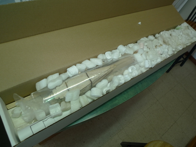
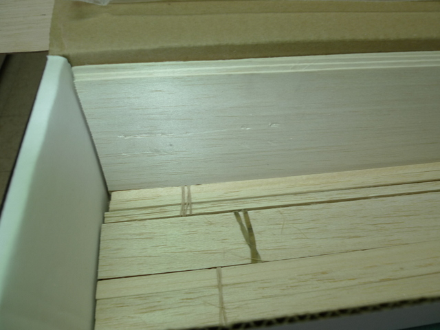
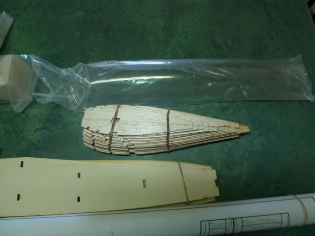
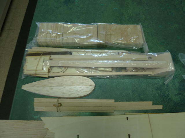
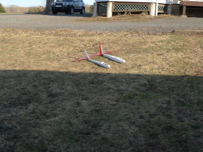
In the box and ready to go with the Aquila Grande
Update April 26 2015
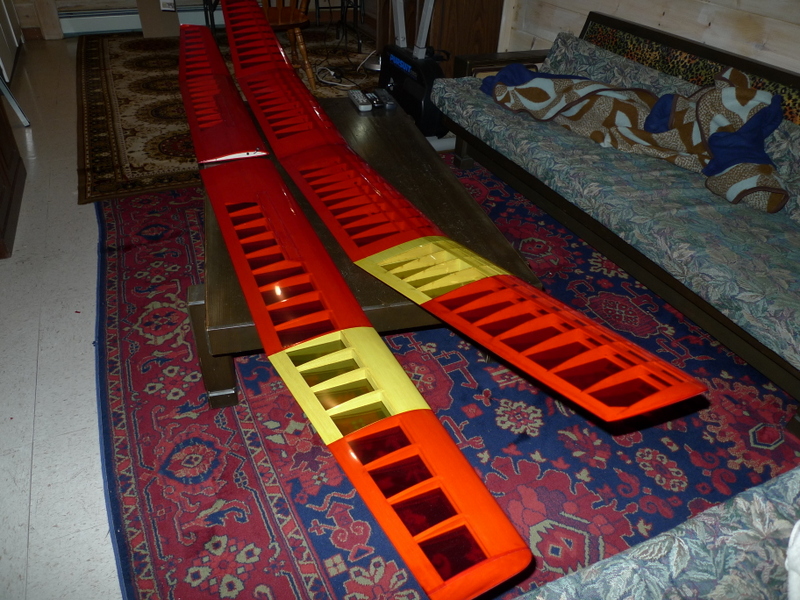
Wings have been covered, the Paragon wing is at the right , appears as a one piece wing. However tip panels are removable
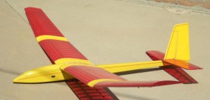
A Nice example of a Paragon
and another
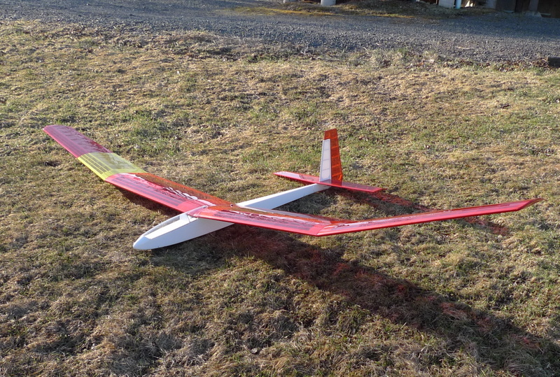
I posted this pic(yellow and red), as I noticed the up sweep on the underside of the wing tips. :):)
———————————————–
wrap joiner boxes
add alignment pin to tip panel
servo operated spoilers 5 bays wide, app 12 inches
tip panel joiners, add CF
Removable elevator/ fin and rudder
tip panel washout 3/16″
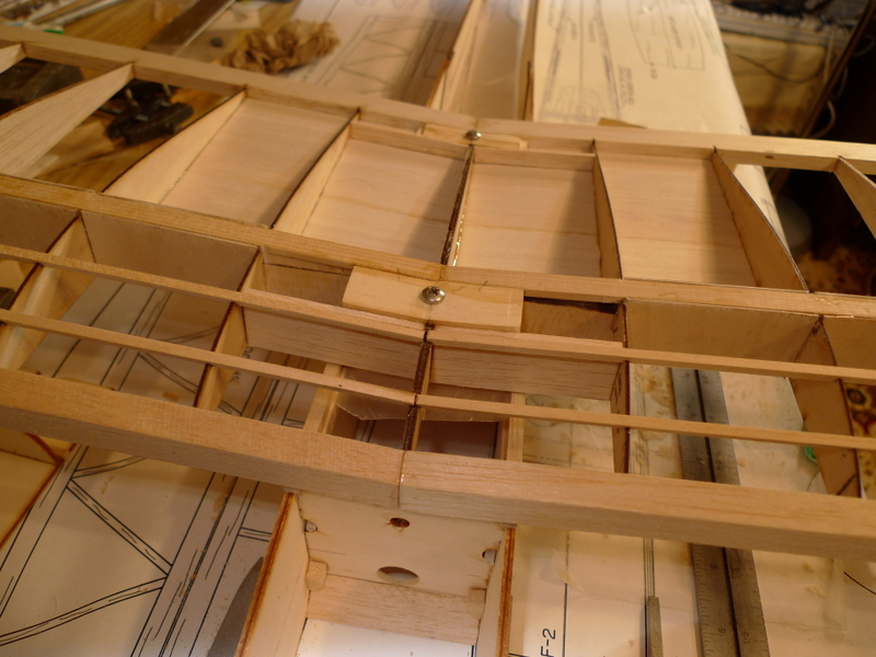
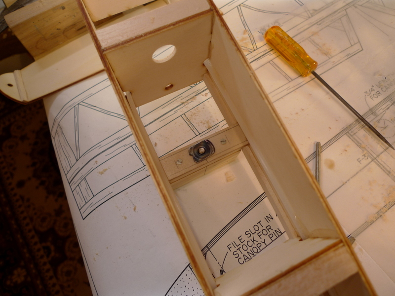
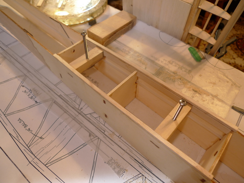
Bolt down wings, two bolts 1 front 1 rear, heads recessed, or 1 bolt at rear and pin at front, still debateable
White fuse
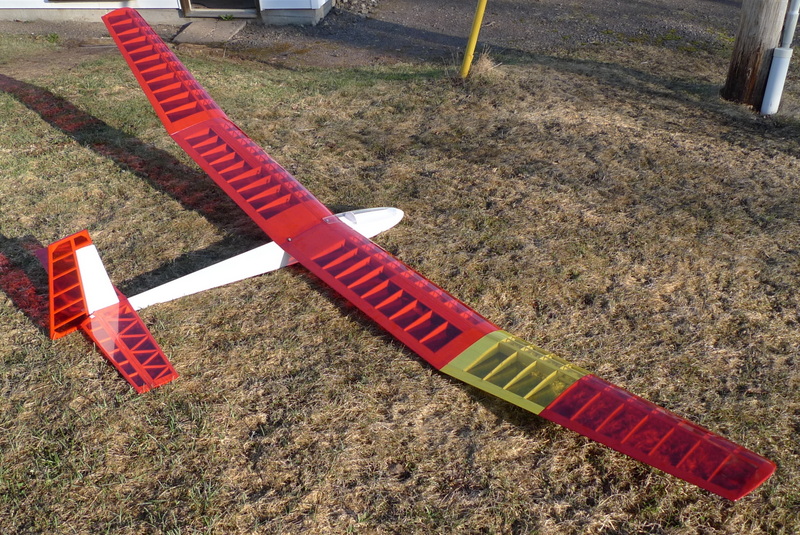
white fin and rudder, red transparent wings with yellow band, right wing
all transparent red elevator
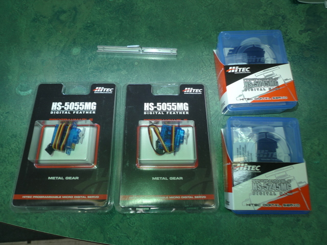
HS-5055MG spoiler servos
HS-5085MG Rudder and Elevator servos
Read on a Thread
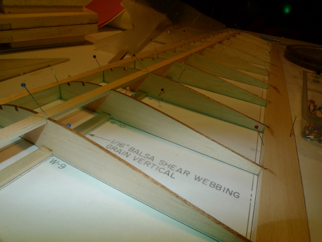
— full width vertical grain balsa shear blocks to be placed between the spars in the entire inner panels.
— kit supplied with 1/16 ply rather then 3/32 balsa ribs for inboard panel
Anything else??
——————-
Note: Some longer lines on the plans have a bow in them. These RCM plans have been copied and reprinted and somehow twisted slightly during this process.
Jan 21
The kit is here complete with for servos..
All well backed, the only thing I can add is the ribs damaged one side of the 1/16″ sheeting.
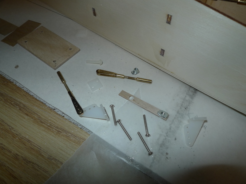
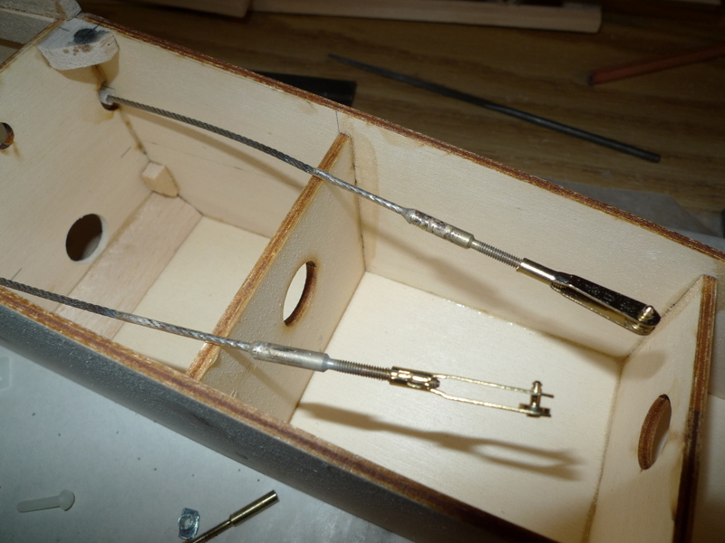
I will replace the Plastic control rods with SS 1/16″ cable..
-add plastic control horns and Sullivan Clevises
=———————
Jan 23
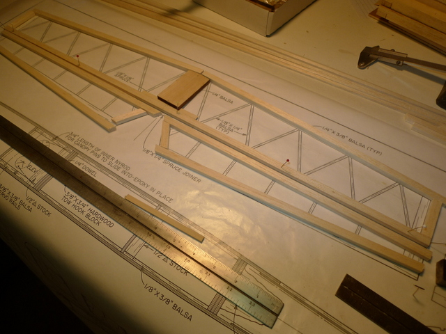
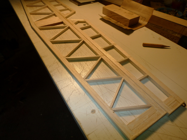
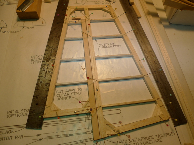
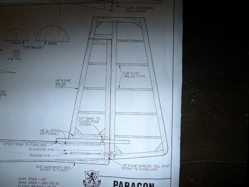
Horizontal stab 1/8 x 1/4 and 1/4 x 3/8 balsa sticks a a bit of spruce to stiffen things up
Note: I had to use a straight edge to place trailing edge stab, the lines have a curve to them.
Vertical stab and fin , same construction as horizontal stab with a spruce fin post
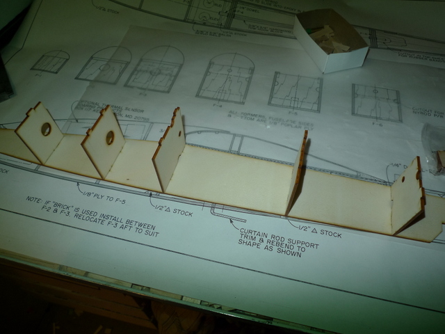
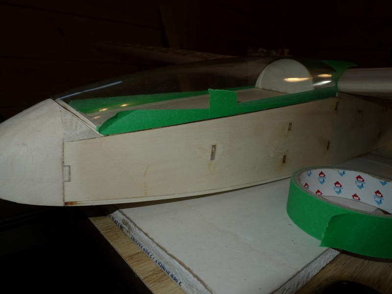
Balsa and ply pieces for fuselage
Formers two of these are the same width, so I can set them at 90 Degrees to the side, and then pull in the front and rear, I’ll mark the centers at the bottom and then I can set everything over a line or two.
Note: The center line on the top view of the fuse is crooked, use a straight edge to draw a straight line, and then place some marks on the plans in the former locations for the widths of the fuse at that point.
——————————————————————————
Jan 25
 Lawrenctown Bluff N.S. Where fellow fliers often toss their planes
HOMEWORK
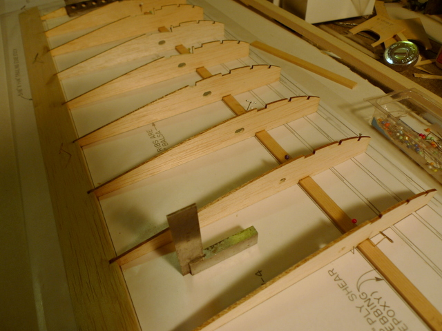
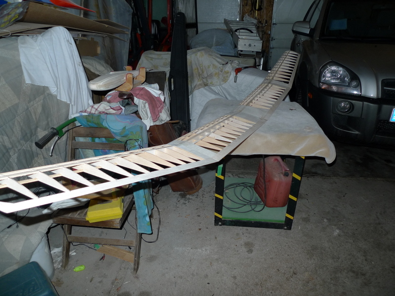
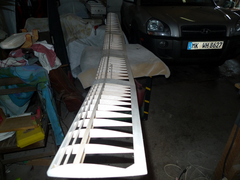
Wing spars
They are spruce 1/8 x 3/8 and all get cut at 29 1/2″ length for the 120″ wing Paragon, both inboard and tip panels
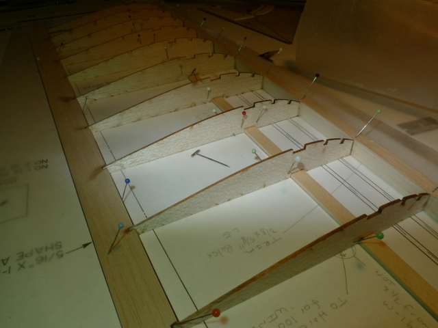
The ribs are nicely done, and I have noticed on the tip panel that the pitch between ribs (w16 – w17) is not 2 1/2 “:)
This may have to do with the 100 Inch version as w17 has the 100″ mark on the plan, or one line is mis- drawn by the width of the rib 3/32”
I like to mark the spars for both wing panels with a rule for this pitch.
Spar width
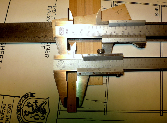
The spar width is not 3/8 ” they are wider nearly 1/32″. Not a problem as I can run them thru the saw and cut them to 3/8″. Another option would be to widen the notch in the ribs to suit. I will choose not to do that as I may sand more towards the front or maybe the rear of the notch. I’d rather use the accuarate notch width and location as a reference.
I could also just push the spars into the notch , however I have seen in the past where this can crush the ribs.
I’m a little puzzled with the height of the last three ribs at the trailing edge.
They are a lot lower then the rest of the set, and I rather thought they would get progressively narrower as I made it to the tip to suit the change in thickness of the trailing edge.
The tip panel is coming together, I’ve added the notches in the LE app. 1/8 ” deep .
Also tapered the TE stock as per drawing it’s narrower back to front at the tip.
————————
Jan 26
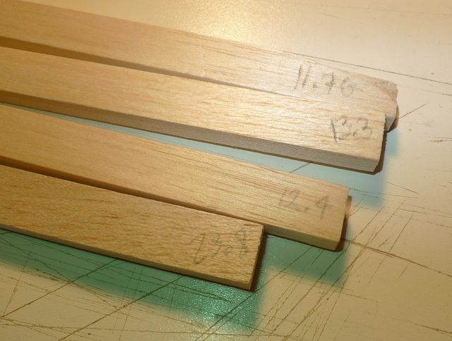
Leading edge stock, It would have been nice If there were 2 pieces that weighed around 24 G.
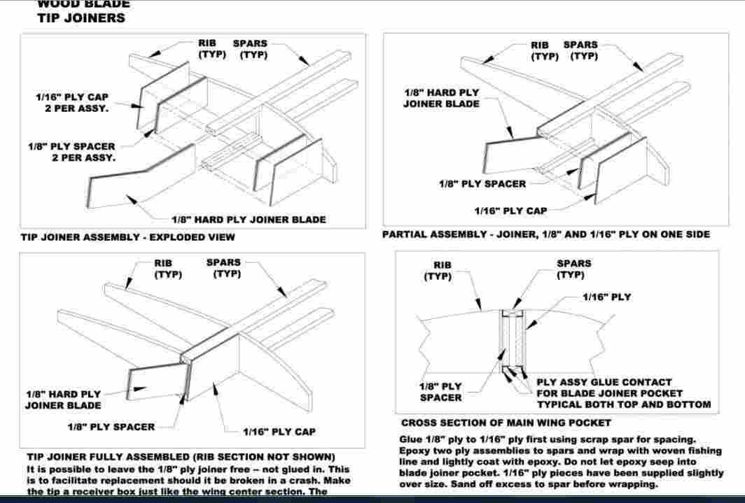
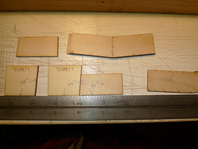 Parts and piece for the tip panel join as well as setting the dihedral and polyhedral angle. Two templates are provide to set the join angle for the root ply ribs, they are shown on the plan, both appear to have the same angle, yet the corresponding angles on the plans are different, and shown as being different.
Also of not is the four spar box sides are also at a different angle then the rib template.
I’m going to clear this beforehand as I want a clean tight panel join.
My plan is to elevate the panel as required per plan and then figure out the angle to lean the ply root ribs.
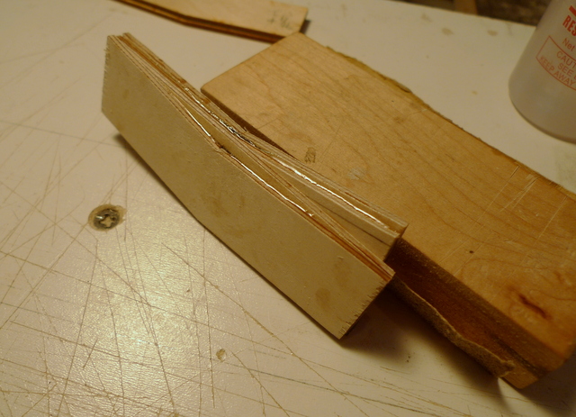
Also going to fabricate a new joiner with cf and a couple pieces 1/16 birch ply.
Here the plans call out the corresponding templates and their intended use
wing tip panel build continues
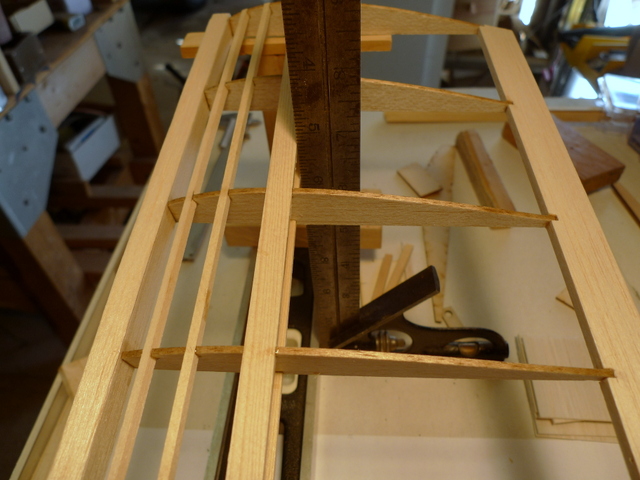
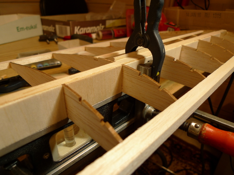
1/8 x 1/8 turbulater spars in place, sheeting between root rib and 1st rib will be added later, a spar box is added and requires wrapping.
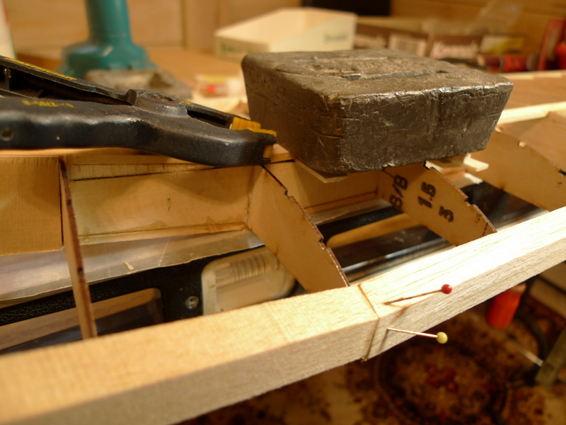
Trailing edge tip is elevated above board to add the 3/16 washout per the build instructions..
Sheeting is later fitted between spars, leading and trailing edges and turbulater spars, I hope the wrapped spar box finishes up nicely as the balsa sheet does not cover the spars
Tip panels weigh app 63 G each, actually .8 G in the difference
————————–
Jan 27
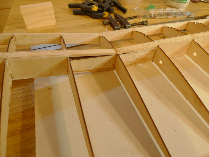
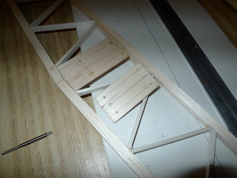
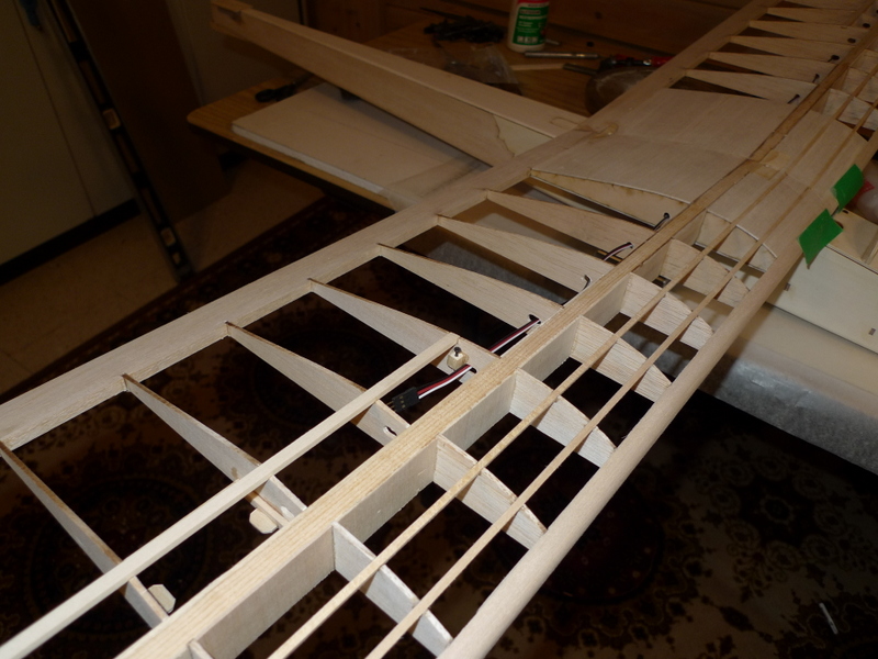
I’ve assembled the ribs that need the additional notch for the spoiler sub spar
Holes and slots added for the spoiler servo wire
Notches added for spoiler blade clearance
Left main panel
Right main panel
———————————
Jan 30
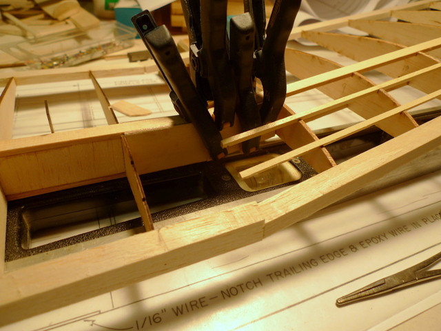
Wing panel join tip to main panel, I made sure I was square with the layup of both panels , and that pays dividents when it came to the panel join.
For alignment, straight spar I’ve set both panels on a level
Left main panel
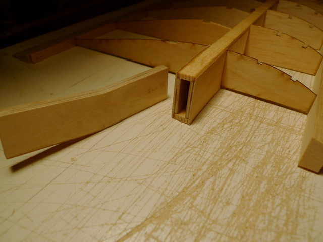
Spar box sides with filler, have to cobble together 4 of these
Joiners, 2 x 1/16 ply as well as a inner filler of .010 CF
As it turns out the 1/8 ” wide tip panel joiner was correct, but neither of the two templates provide where at the correct angle for setting the two ply root ribs ay the polyhedral join.
Inboard joiner box on right panel, still needs to be wrapped
——————-
Jan 31 2015
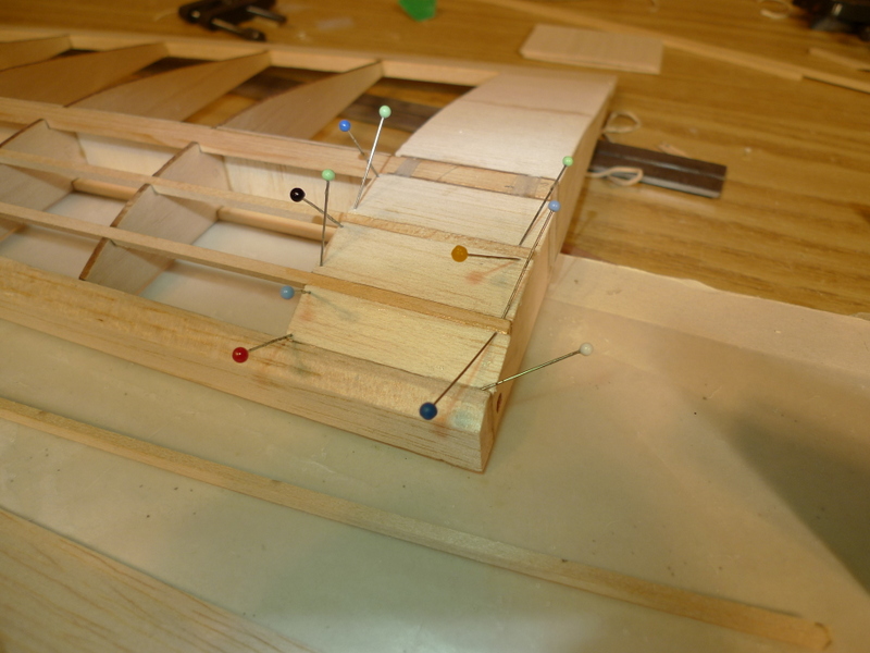
Seems like I have been working at the joiner boxes for days.
Tip panels root rib in place, it’s been elevated 1/16″ for the underside sheeting which I’ll add later
While waiting for some glue to set , I shaved off some leading edge material from one of the main panels.
Joiner box sides for tip panel are glued in here
Turns out someone else had already built spar joiner boxes like I have.
Oh well 🙂
————————-
Feb 13
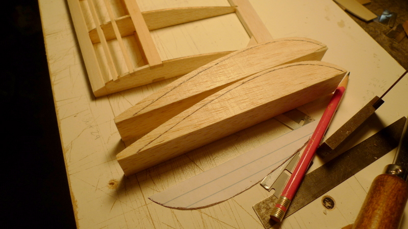
Tip blocks, are a little larger then needed.
Tips glued in place
Three choices for hinges that I have here for the rudder and elevator:)
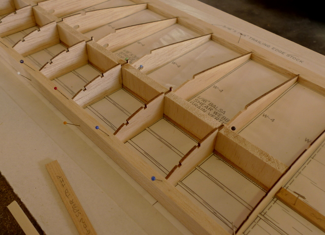
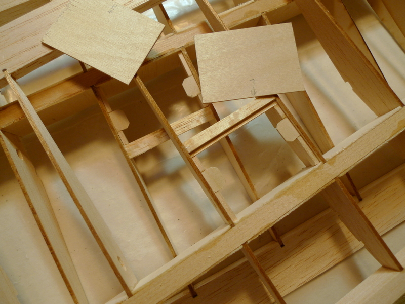
Ply shear webs are not wide enough, the balsa ribs where replaced by 1/16 ply ribs in the kit in a number of locations at the inboard end of the center panels and as a result the webs are missing a bit of meat
Thankfully I’ve got plenty of 1/16 ply so I cut some new parts, 16 of then all together
Feb 17
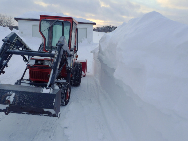
Snow, seems like February is all about snow, the last storm left us with over 2 feet, and I still have to clear the lane up to the Chalets
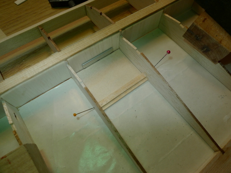
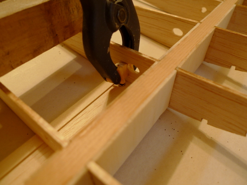
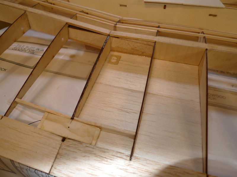
Back to the Main panel, and balsa shear webbing. This is a key area as I’ve added openings for spoilers, and the leading edge of the opening needs a piece of balsa added. The tops of the balsa shear webs will not work,
Mar 13
Tip panels shear webbing, and inboard end sheeting
Right tip
Mar14
spoiler servo install, as well as spoiler bay sub spar
Mar 17
with most of the work done on the inboard panels, I proceeded with the join.
Trailing edge and leading edge as well as spars are trimmed up for a nice fit, the epoxy is added and all the work is done on a 4 ft level
One tip is raised 4 3/4″ and all went together really well
Mar 18
Spoiler blades stops
Root ribs at dihedral main panel center
Spoiler blade stop in position underside
Load beam location, forward of main spar
Removal of two ribs at load beam location
Cleaned up ready for installation of load beam
Mar 21
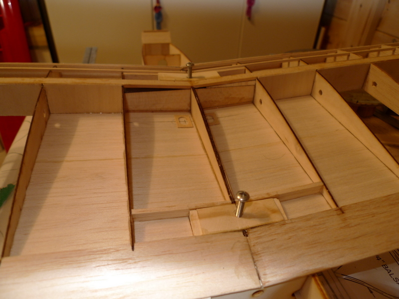
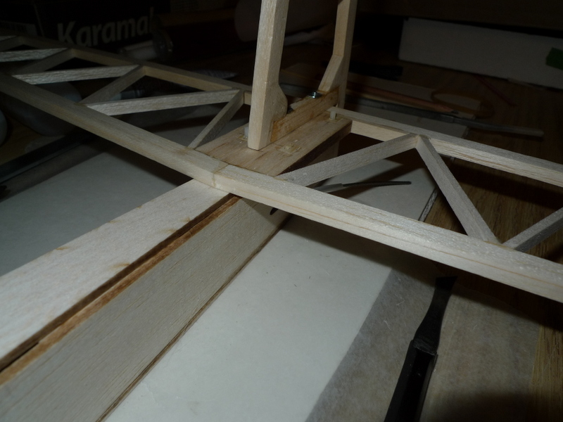
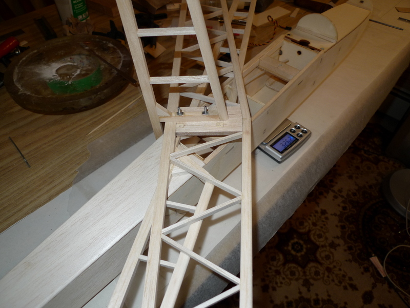
Nylon screws, I will use these later to secure the horizontal stab to the fuse
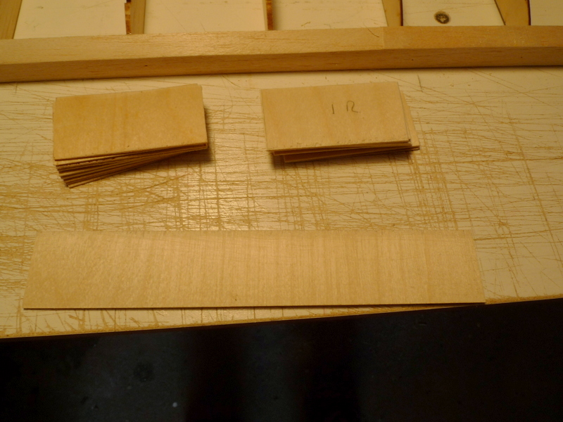
Filler sheet
Turbulator spars one side of center panel
Mar 22
Load spreader, 1/8 ply and a piece of beech to give then moth a strongback.
The 1/8″ ply is keyed to fit into slots in the fuselage side.
1/16″ balsa filler sheet , center panels tips
Mar 24
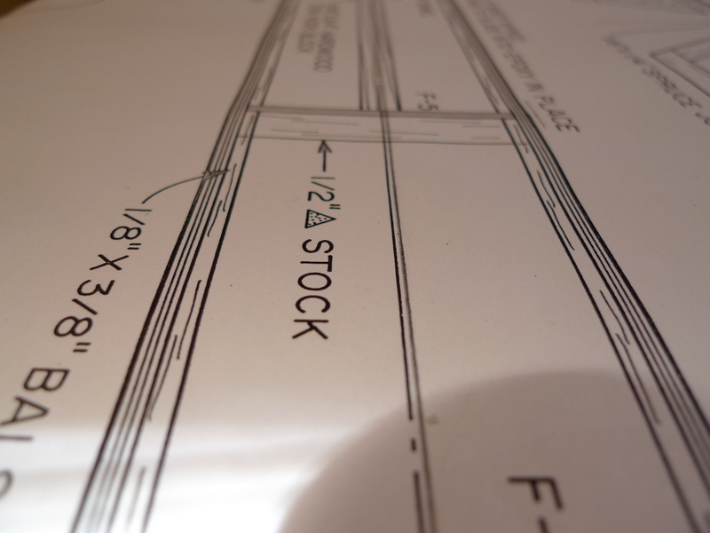
Fuse plan detail.
TIP
add a straight line down the center and line the formers up with it.
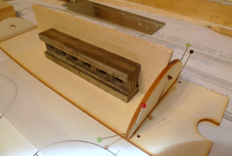
rearmost former
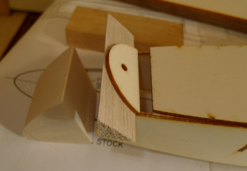
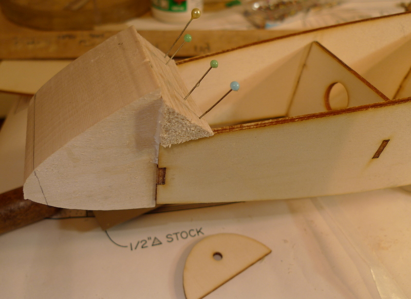
forward former and 1/2 tri gussets
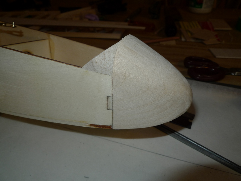
nose block . 3/4 tri gusset here was not found in kit
Mar 25
Canopy frame, and supports.
Canopy will get secured with magnets to fuselage
Mar 27
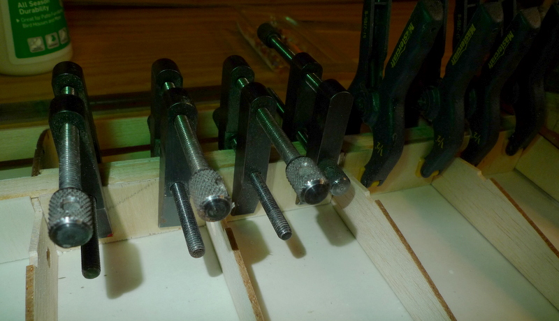
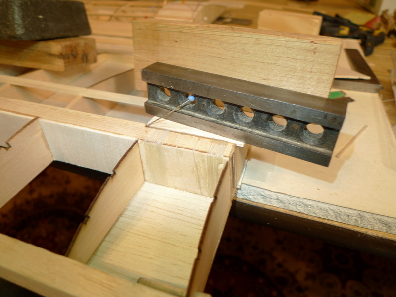
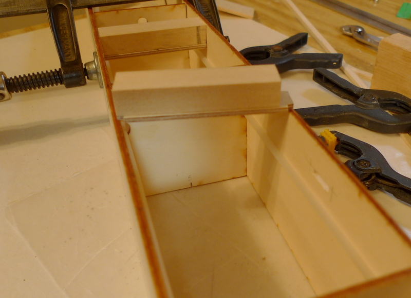
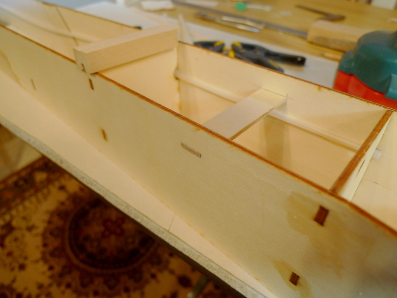
wing hold down Technique
I spend a lot of time prepping and marking centerlines here.
Nice to have everything come out straight and of course level wings
Mar 28
I finished up sheeting the center panel, at the wing panel join and moved on to other Fuselage parts.
A shiny new tow hook and channel arrived today in the mail, what an opportunity to add that to the lower fuselage sheeting.
The plans show a wood screw type L hook as a suitable arrangement for a tow hook however I was never a fan of those.
I fabricated some 1/8 ply parts to connect the channel to the fuse bottom
Mar 30
The fun part is here, sanding and finishing.
Mar 31
Wings and more wing.
They are very light, or that’s what I believe, just north of 21 Oz
and fragile to sand,
April 01
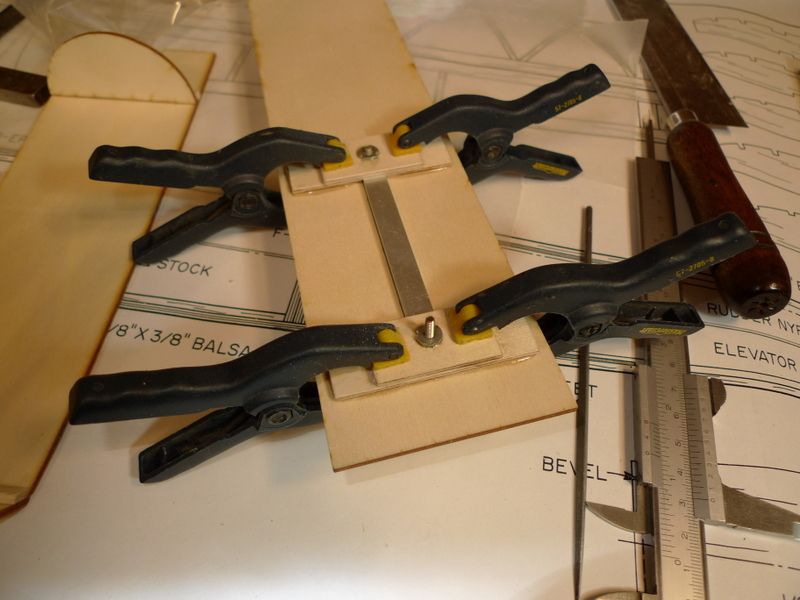
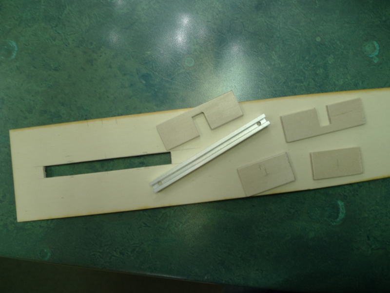
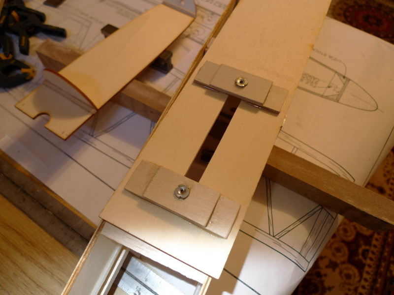
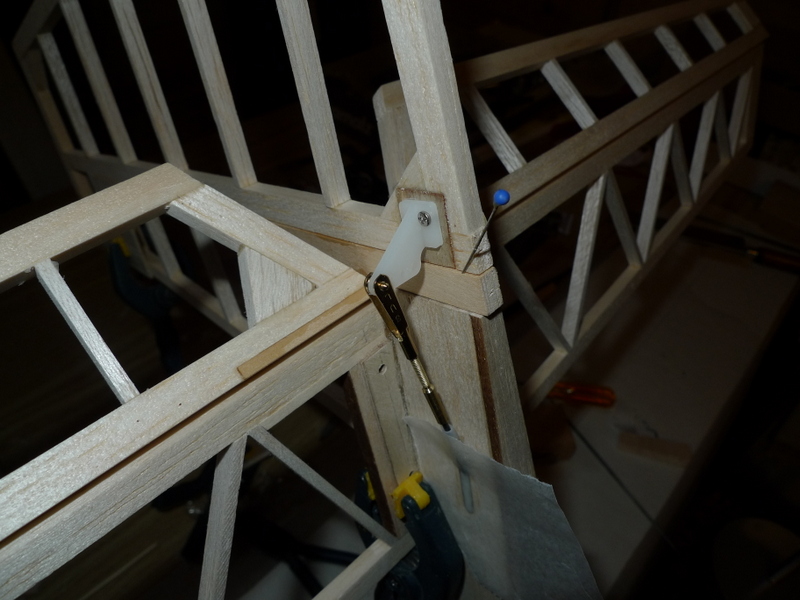
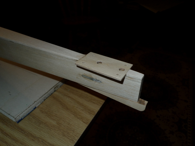
Horizontal stab mount with a plate and four screws. The fin will be bolted to the stab from the underside.
Adding the bottom rear balsa sheet..
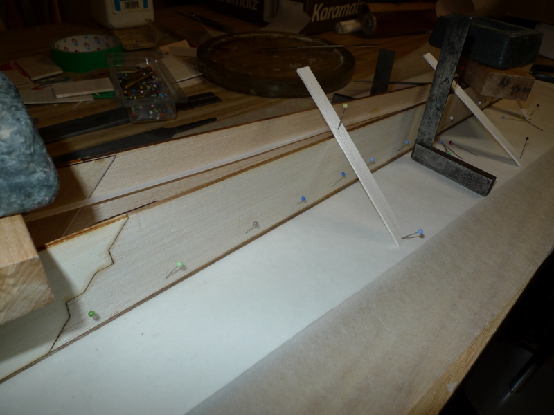
One side a a slight warp , about 1/8 to 3/16 inch over it’s length so I had to hold things square when I glued the bottom sheet on
April 1
April 02
April 7
Not a lot of visible progress at this point. I have done some work on sanding everything
– fitting plastic canopy to the frame
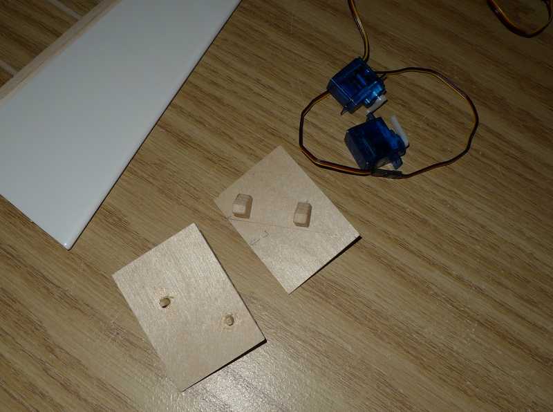
– building servo tray
– reinforcing areas on vert and hori. stab where horns set
– sanding bevels onto one edge of tail feathers.
– sanding and shaping fuse for paint
– prepping wing center panel for layer of FG cloth
April 19
After the second coat of paint..
Some pinholes are starting too show and they will need to be filled
April 24
I set then on the scale right after I covered them 102.3 Grams each..
That’s quite remarkable.
April 27
Spoiler servos and access hatches
Vertical fin and a splash of white.
April 28
April 29
After 117 Hours of building I can see the end of the road.
For anyone who’s ever built a plane and put in these hours , there is a sense of attachment somehow..
However this Paragon is gonna go into a box and head west.
I’d like to take the time to fly it, but then it won’t be new anymore..
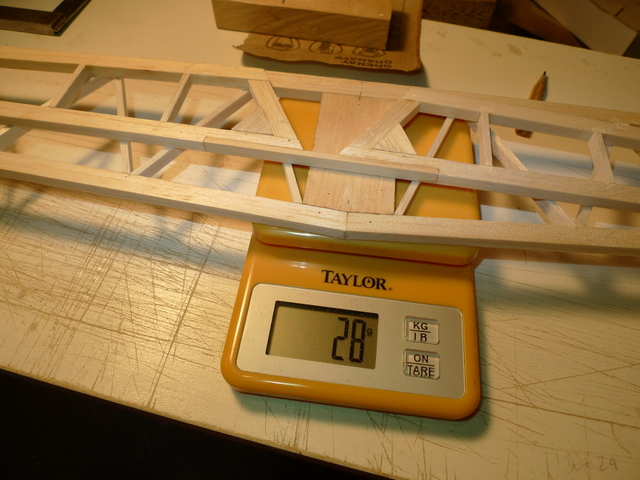
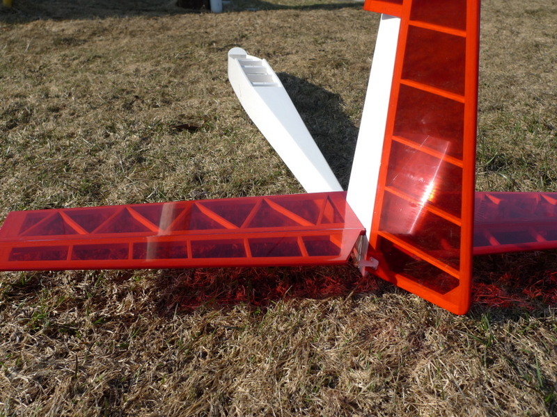
Here are a couple pictures of the horizontal and vertical stab.
I still need to cover the fixed part of the hor stab, and add the hinge.
I was fortunate to have enough red , last night I thought I wouldn’t have enough and thought I may have to add some blue or orange! :):)
May 04
Some more assembly work, soon this will be a standard ARF
With it’s stable mate for the last few months, an Aquila Grande
May 06
Balanced at center of spar
Weight 1575 G
Including:
Receiver 38G
Eneloop 107G
Lead 179G
1575 G ———– 55 . 6 Oz
Wing Area 1080 Sq In or 7.5 sq ft
Wing load of 7.4 oz/sq ft


